 40G/100G Optical Transceivers
 25G Optical Transceivers
 10G Optical Transceivers
 155M/2.5G Optical Transceivers
 1G Optical Transceivers
 1G BIDI Optical Transceivers
 Dual-Rate Optical Transceivers
 FC 16G/32G Optical Transceivers
 CWDM Optical Transceivers
 DWDM Optical Transceivers
 SGMII Port Optical Transceivers
 XFP Optical Transceivers
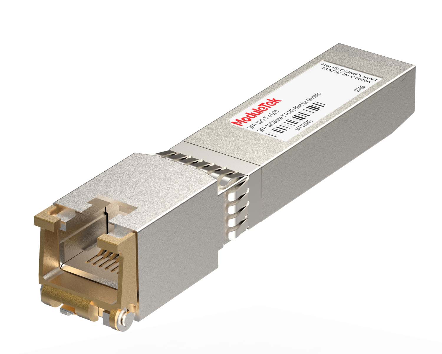 100M/1G/10G Coppers
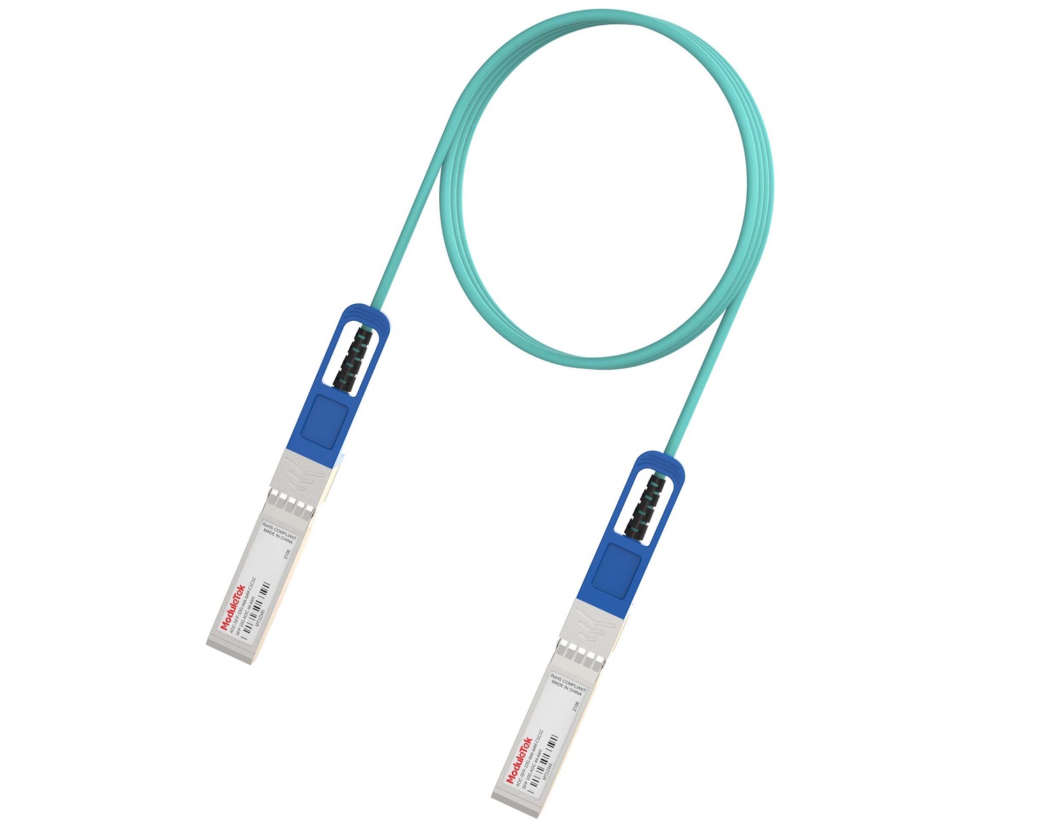 Full-Rate AOC & Breakout Series
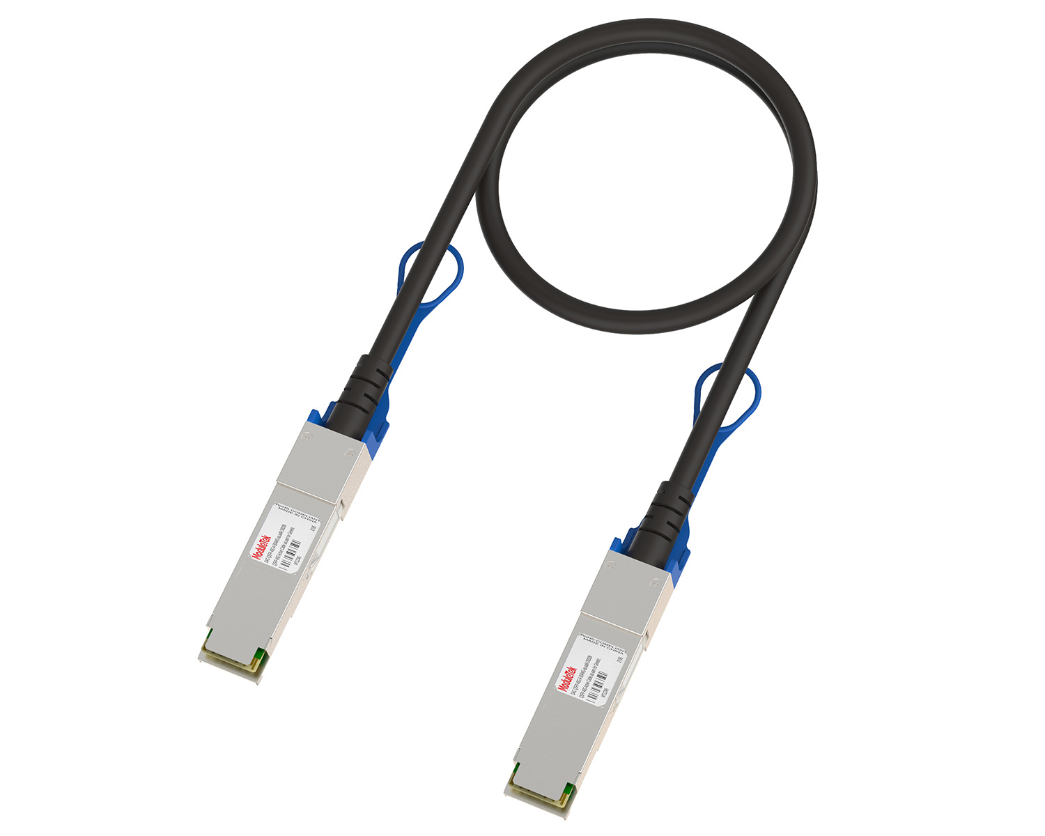 10G/40G Active DAC Series
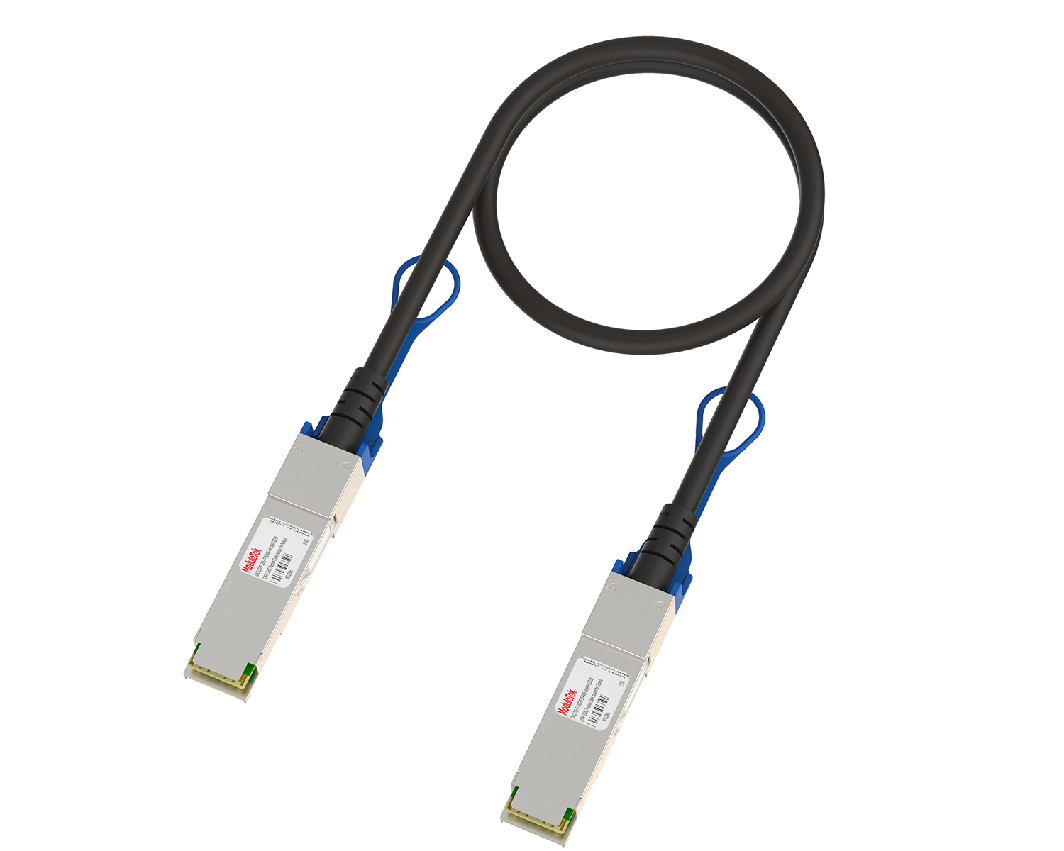 Full-Rate Passive DAC Series
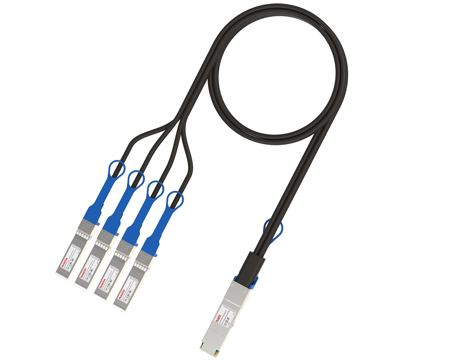 40G/100G Passive Breakout DAC Series
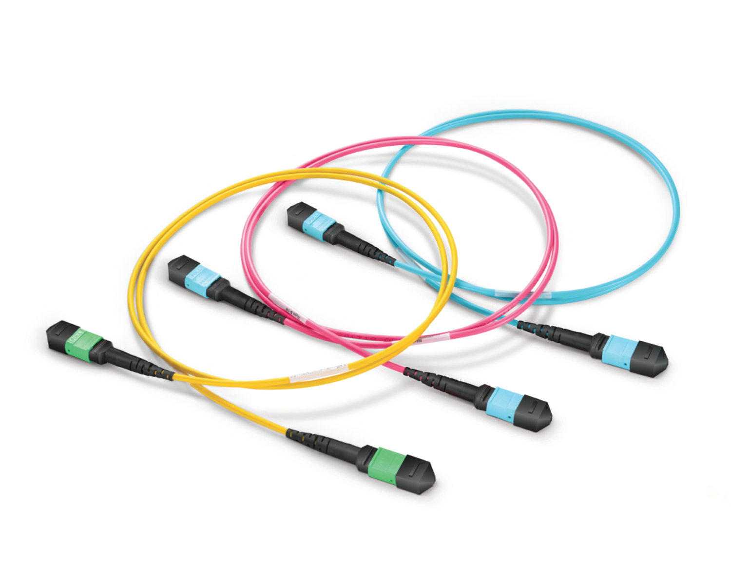 Regular/MTP-MPO Fiber Patch Cords
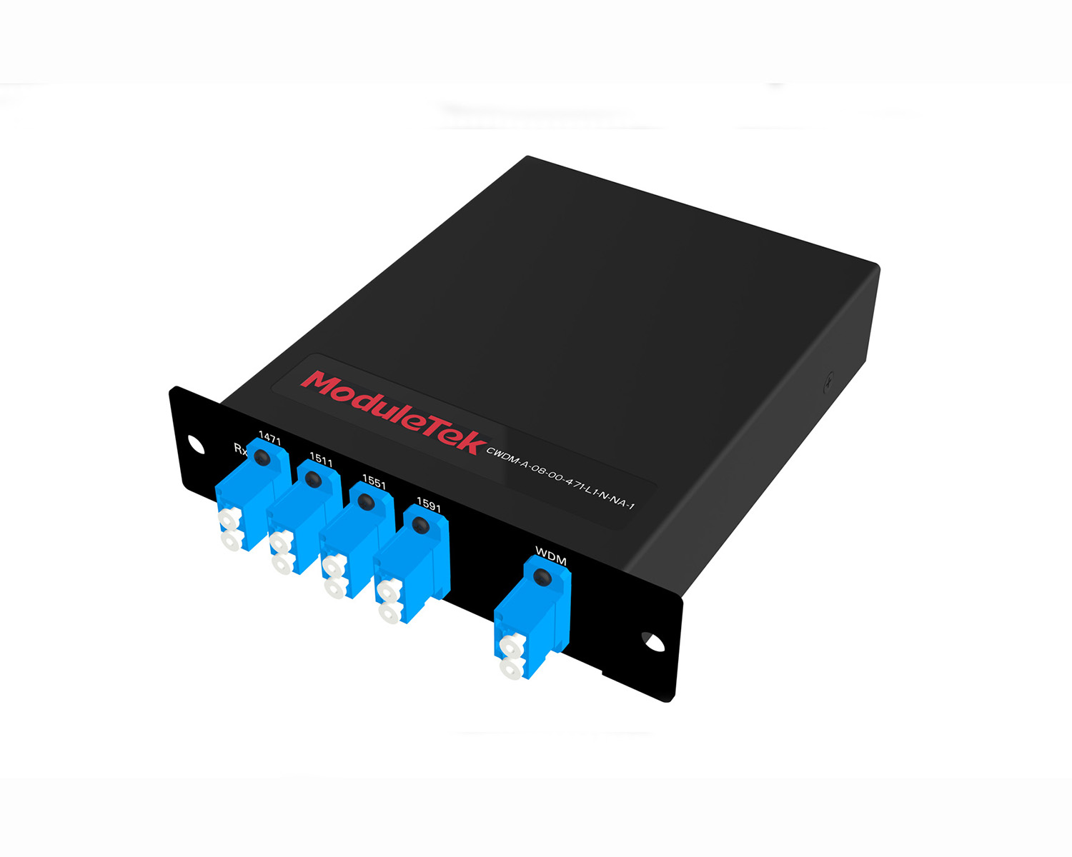 MT2011
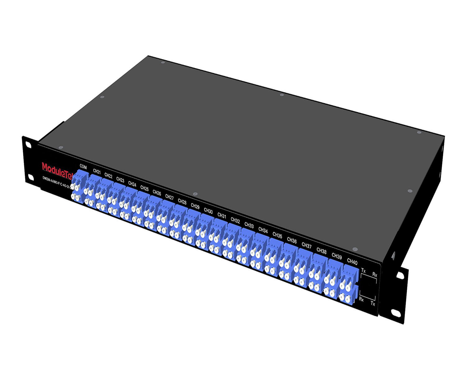 MT2010
 CodingBox
 QSFP to SFP Adapter
Recognize MPO II : MPO Fiber Optic Patch Cords
Time: 2020-03-29
MPO fiber optic patch cords are manufactured by assembling MPO connectors with fiber optic cables in various configurations. They are widely used in high-density integrated fiber optic cabling scenarios, such as the interconnection of 40G/100G transceiver modules and internal/external optical communication devices.
MPO fiber optic patch cords are divided into adapter type and non-adapter type according to the connector configuration.
There are multiple variants of adapter type MPO patch cords, which are fan-out patch cords processed from ribbon or bundle MPO cables via plastic round/square branch sleeves. Generally, they can be split into 2–24 core branch cables with 0.9mm or 2.0mm outer diameter.
The branch connectors can be customized according to customer requirements, with optional types including FC, LC, SC, etc. The total length of the MPO patch cord is customer-specified, and the branch length can also be customized within a process-limited range (the branch length is generally not more than 3 meters).
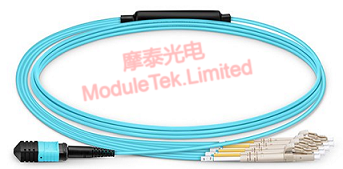
Figure 1 Physical Diagram of MPO-LC Adapter Type Fiber Optic Patch Cord (2.0mm Branch Diameter)
Non-adapter type MPO patch cords are equipped with MPO connectors at both ends, dedicated for interconnection between MPO ports of devices/modules. According to the TIA-568 standard, non-adapter type MPO patch cords have three wiring specifications: Type A, Type B and Type C, with distinct core alignment and keyway orientations:
Type A patch cords adopt straight-through fiber bundles, with a keyway-up MPO connector at one end and a keyway-down MPO connector at the other. The fiber cores are in one-to-one alignment at both ends of the patch cord (i.e., the 1st core hole of the left connector corresponds to the 1st core hole of the right connector).
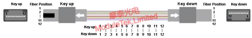
Figure 2 Type A Straight-Through Wiring Sequence Definition
Type B full-crossed patch cords use fully crossed fiber bundles, with a keyway-up MPO connector at both ends. The fiber cores are reversely aligned at both ends (i.e., the 1st core hole of the left connector corresponds to the 12th core hole of the right connector). This type is the most commonly used for optical module interconnections, such as the optical port interconnection between QSFP-SR4 and QSFP-SR4 modules.
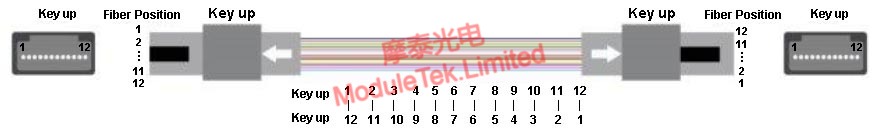
Figure 3 Type B Full Crossover Wiring Sequence Definition
Type C pair-crossed patch cords adopt pair-crossed fiber bundles, with a keyway-up MPO connector at both ends. Adjacent fiber core pairs at one end are reversely aligned with the corresponding pairs at the other end (i.e., the 1st core hole of the left connector corresponds to the 2nd core hole of the right connector, and the 2nd core hole of the left connector corresponds to the 1st core hole of the right connector; the same cross rule applies to subsequent core pairs).
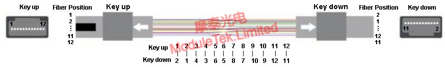
Figure 4 Type C Pair Crossover Sequence Definition
In practical applications, we will reasonably select the type of MPO patch cord according to customer requirements and on-site application conditions to ensure the accuracy of fiber optic network polarity.
Moduletek provides a full range of customizable MPO fiber optic patch cords to meet different application scenarios. Welcome to place your orders!
For further inquiries about the above content, please contact us at: sales@moduletek.com


