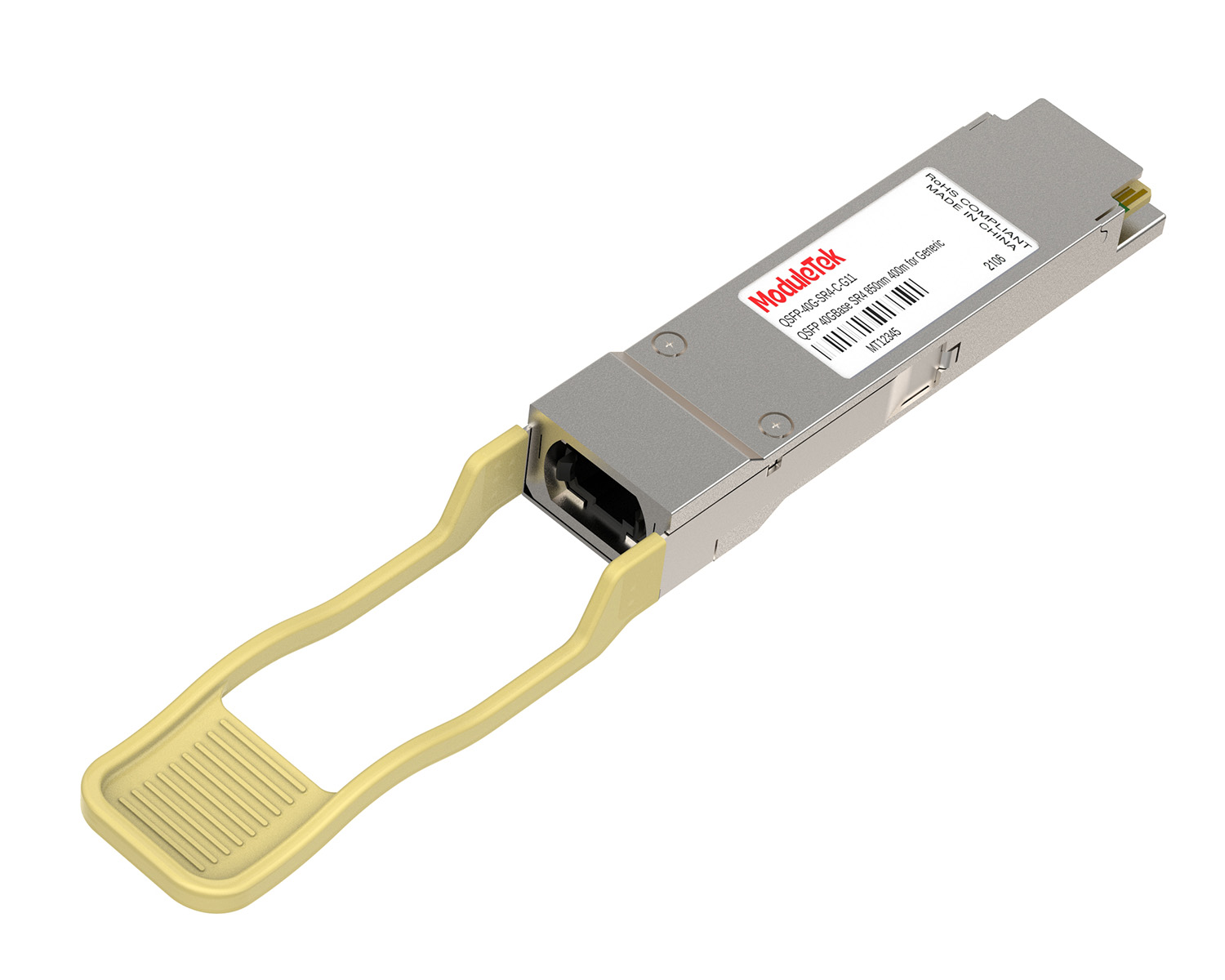
 40G/100G Optical Transceivers
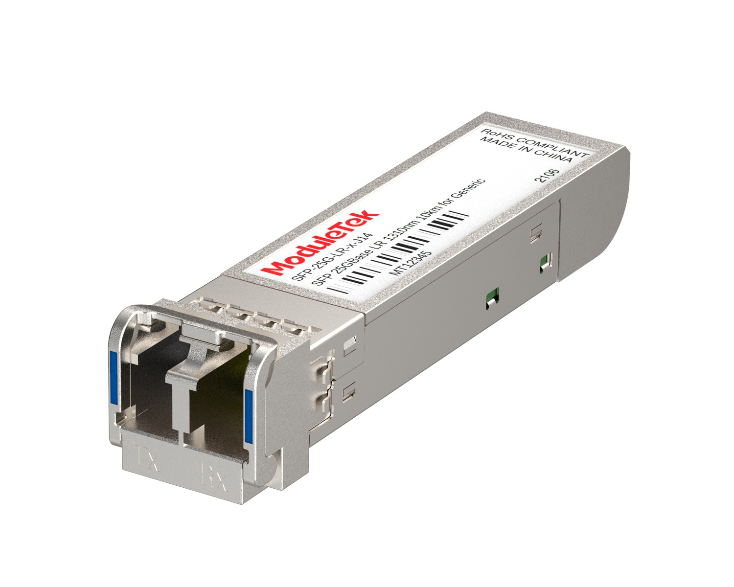 25G Optical Transceivers
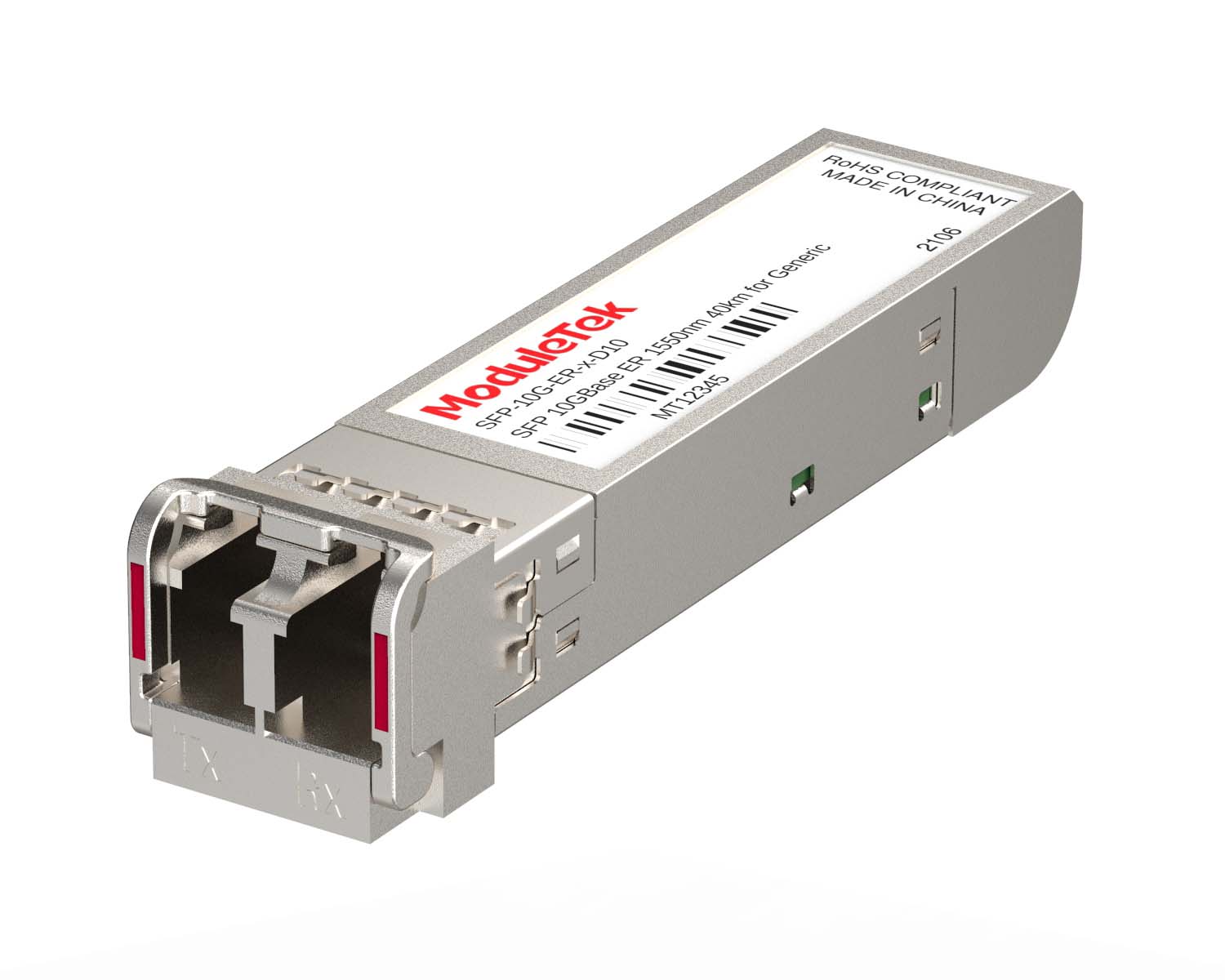 10G Optical Transceivers
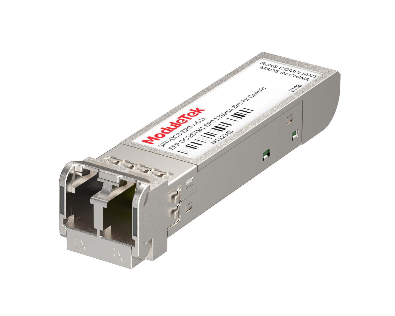 155M/2.5G Optical Transceivers
 1G Optical Transceivers
 1G BIDI Optical Transceivers
 Dual-Rate Optical Transceivers
 FC 16G/32G Optical Transceivers
 CWDM Optical Transceivers
 DWDM Optical Transceivers
 SGMII Port Optical Transceivers
 XFP Optical Transceivers
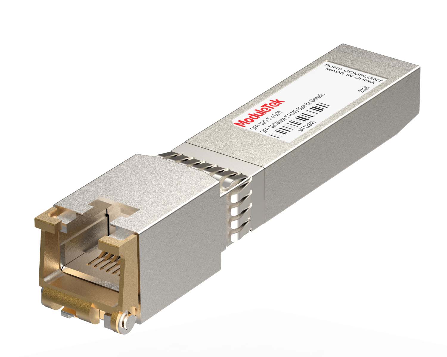 100M/1G/10G Coppers
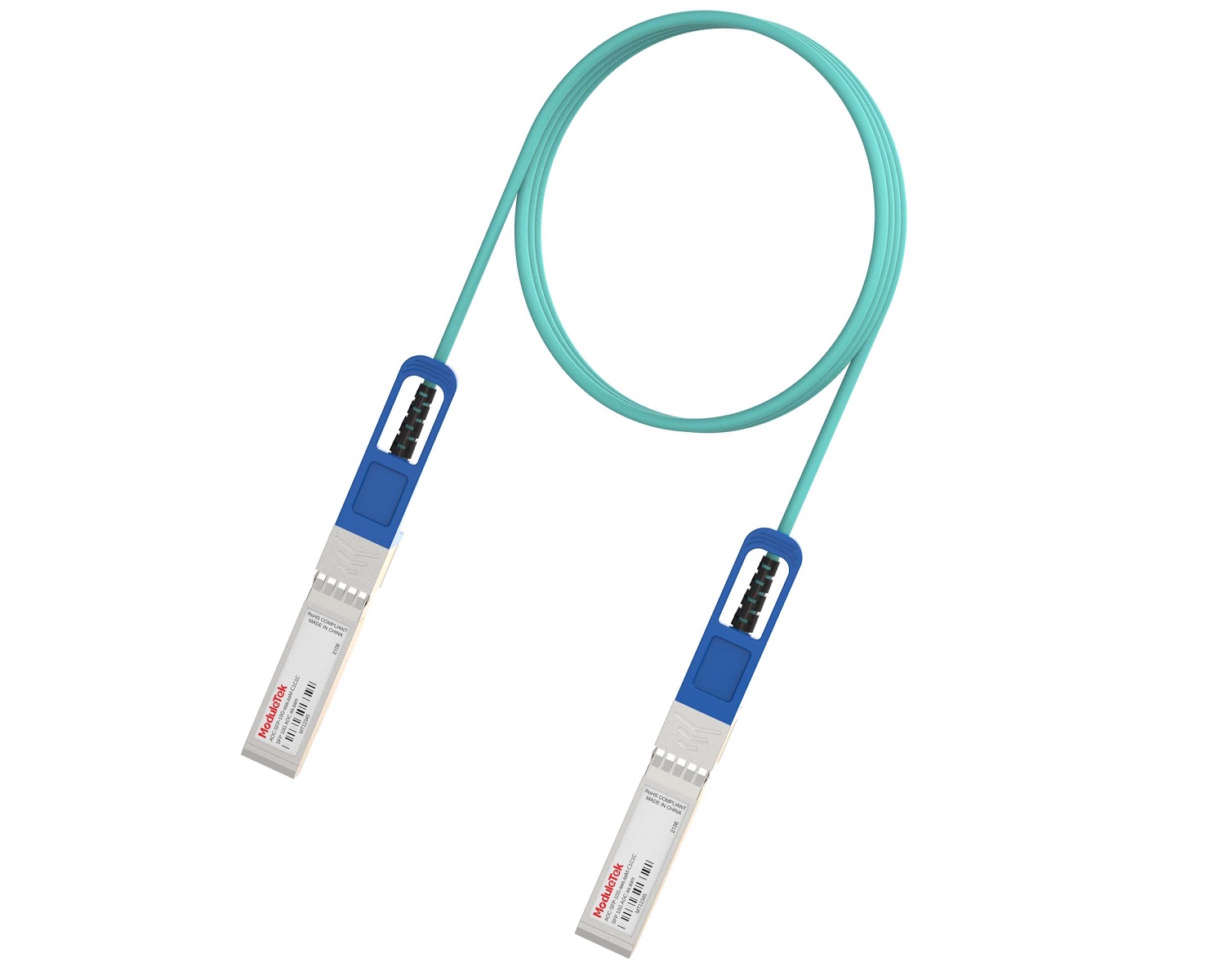 Full-Rate AOC & Breakout Series
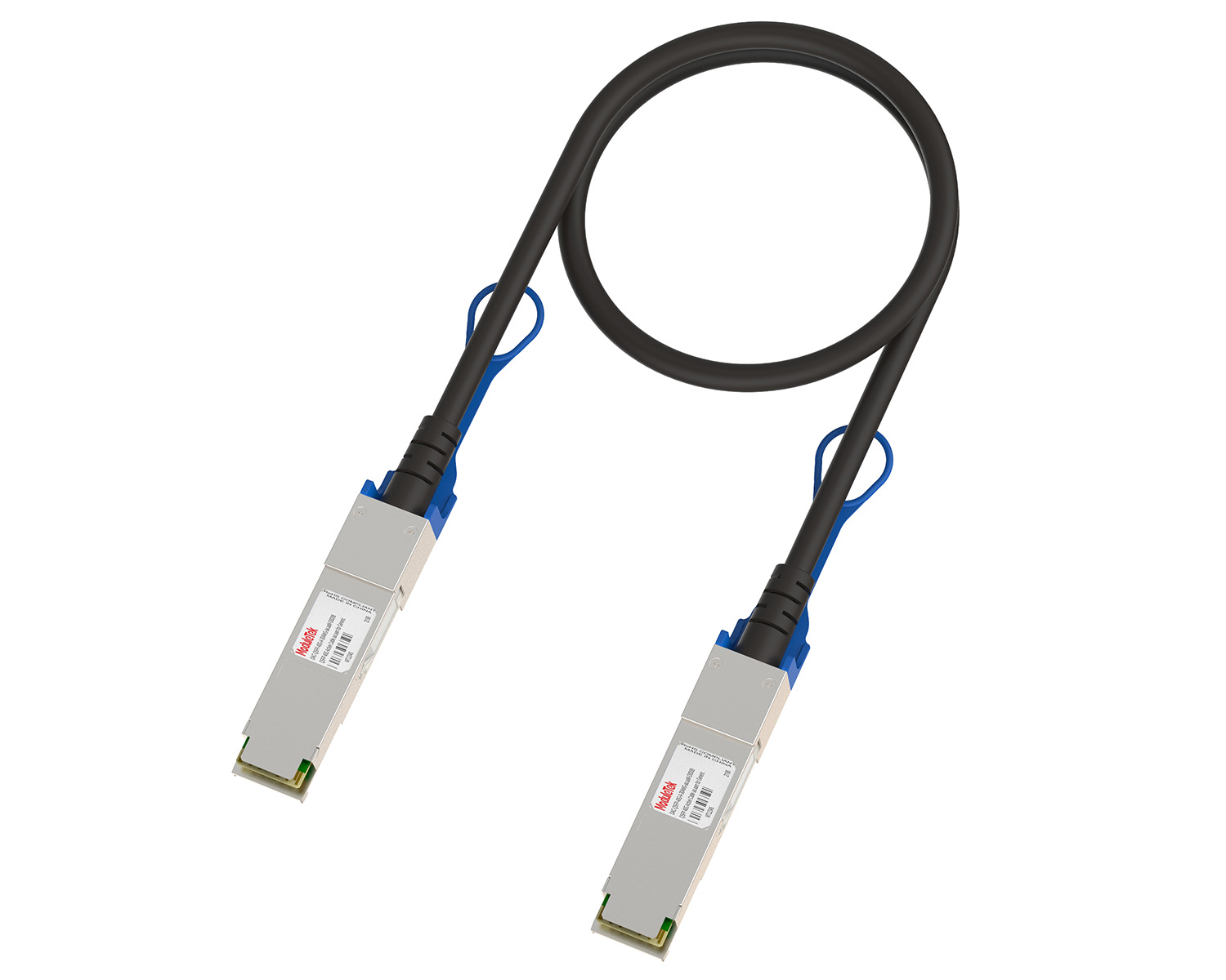 10G/40G Active DAC Series
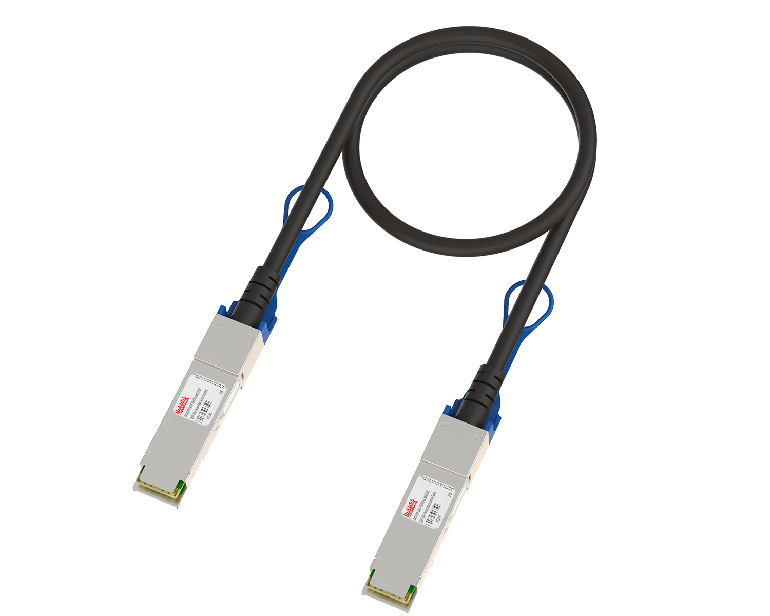 Full-Rate Passive DAC Series
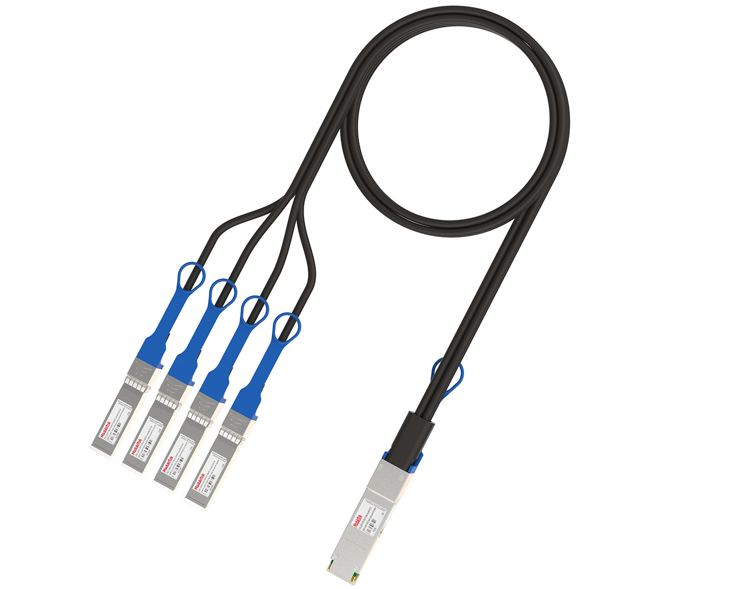 40G/100G Passive Breakout DAC Series
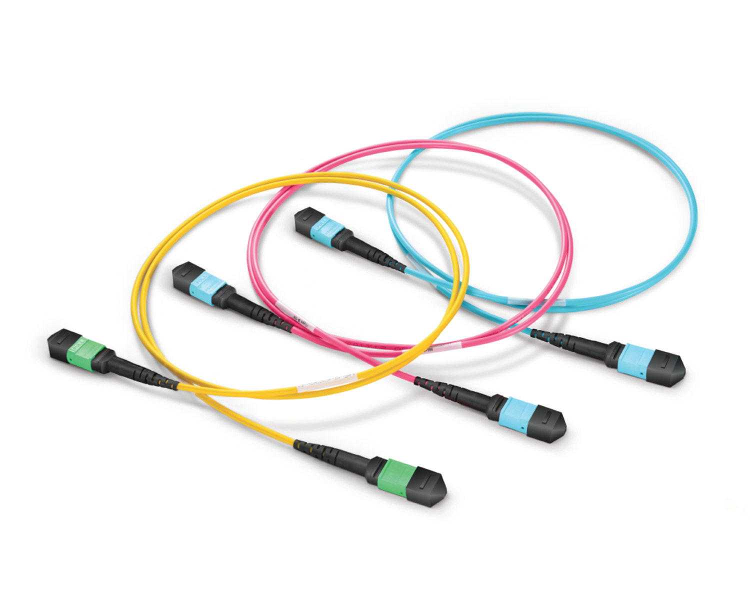 Regular/MTP-MPO Fiber Patch Cords
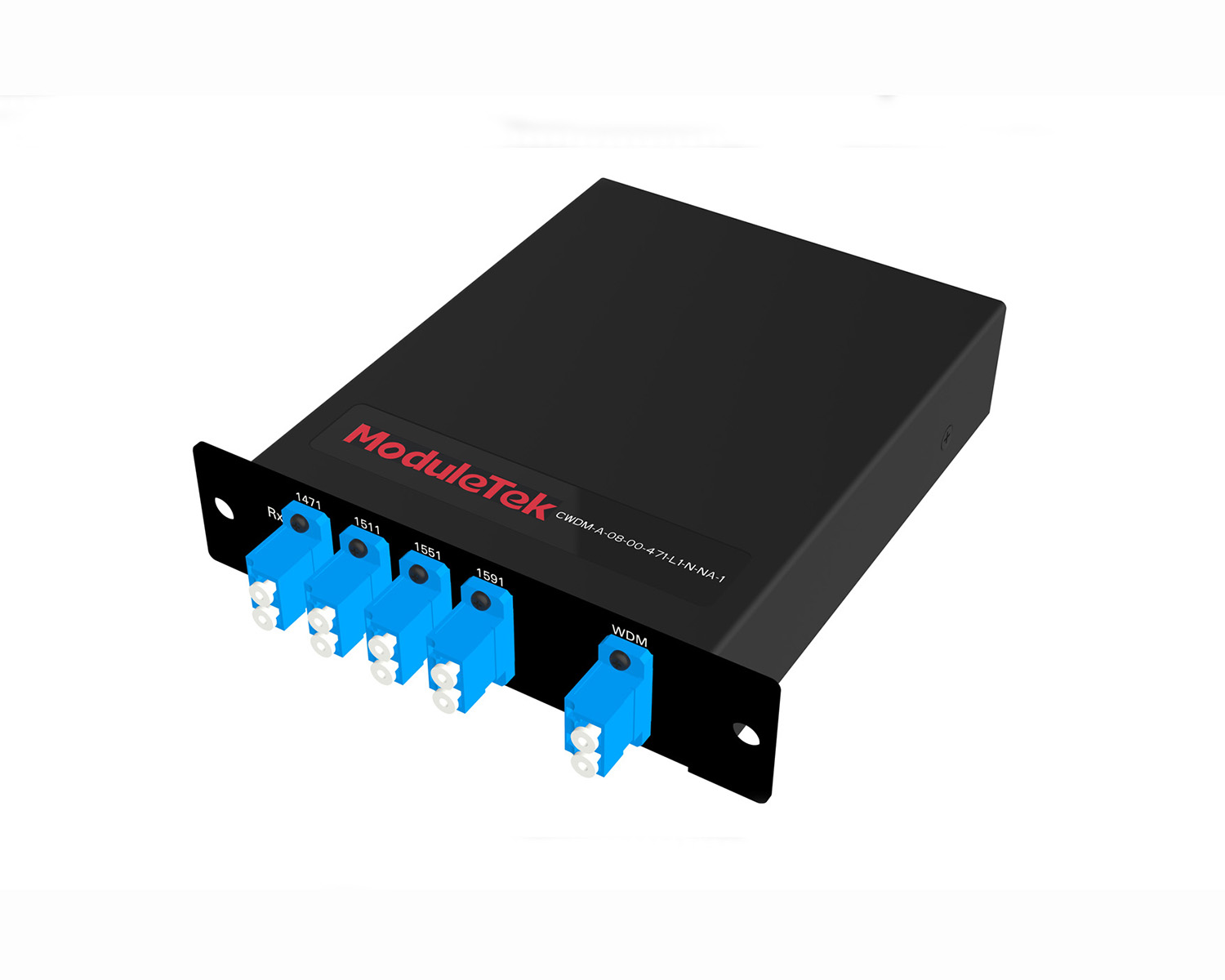 MT2011
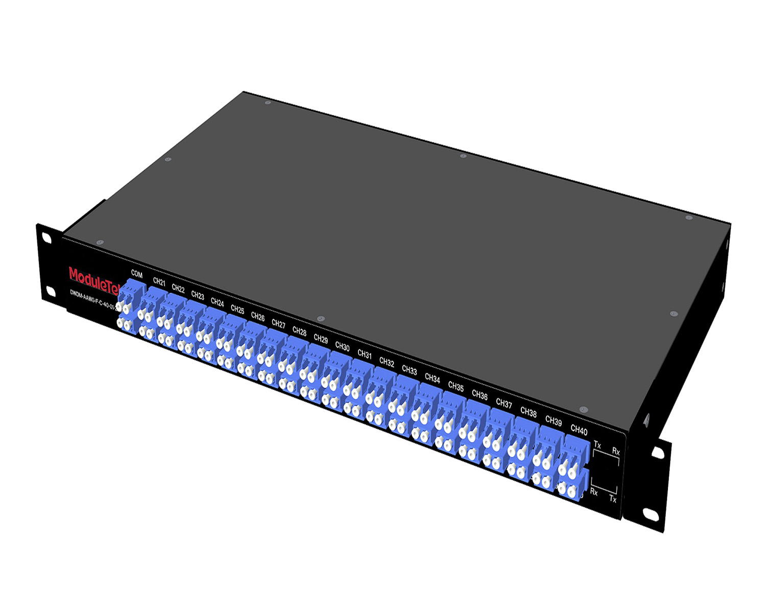 MT2010
 CodingBox
 QSFP to SFP Adapter
 首页 > Home > Application Notes > Optical Module Application: Common Problems & Troubleshooting Methods
Optical Module Application: Common Problems & Troubleshooting Methods
Time: 2023-06-26
Based on typical issues encountered with optical modules in daily switch applications, this document summarizes basic troubleshooting steps for resolving common faults:
1. Check compatibility between the optical module and switch
Most switch brands have specific compatibility requirements, especially when using third-party optical modules. First verify that the module is compatible with your switch. You can confirm proper recognition by reading port identification information via switch commands.
Example: After installing an SFP-10GB-SR module into a Cisco 4500 switch, use CLI commands to check whether the module is recognized. If the switch fails to detect the module correctly, the port will not work properly.
(If the module cannot be recognized and causes communication failures, please contact your optical module supplier for support.)
2. Check fiber type matching (if module is recognized but LINK status is abnormal)
If the switch identifies the module normally but the LINK indicator is incorrect and communication fails, verify the fiber type:
• Multi-mode optical modules require multi-mode fiber (usually orange or aqua green), marked as 62.5/125 μm or 50/125 μm on the cable jacket.
• Single-mode optical modules require single-mode fiber (usually yellow), marked with G65xx specifications.
Using mismatched fiber types will prevent normal transmission.
3. Check optical link attenuation and received optical power
Ensure the received optical power at the far end falls within the module’s specified receive sensitivity range. If the received power is below the sensitivity threshold, issues such as link instability, high BER, and CRC errors may occur.
Module sensitivity and power specifications are clearly listed in the manufacturer’s datasheet.
You can verify power levels in two ways:
• Use a handheld optical power meter to measure actual transmit and receive optical power.
• Use the built-in DOM (Digital Optical Monitoring) function of the module to read received optical power from the switch.
4. Clean fiber end faces if received power is too low
If received optical power is below the rated sensitivity, the optical link may be faulty:
• Check for loose fiber connections.
• Inspect and clean contaminated fiber end faces using professional fiber cleaning tools, or temporarily use dust-free paper for cleaning.
5. Verify switch port configuration
If optical attenuation is normal but the link still fails, check the switch port settings:
• Some switches use combo SFP/RJ45 ports, which require manual optical port configuration.
• Some ports are multi-rate multiplexed (e.g., 25G/10G shared ports). When using 10G modules, the port must be manually set to 10G speed.
6. Further support
For additional optical module application issues, please contact us via email for online technical support.
Moduletek Limited is at your service!
For further inquiries about the above content, please contact us at: sales@moduletek.com


