
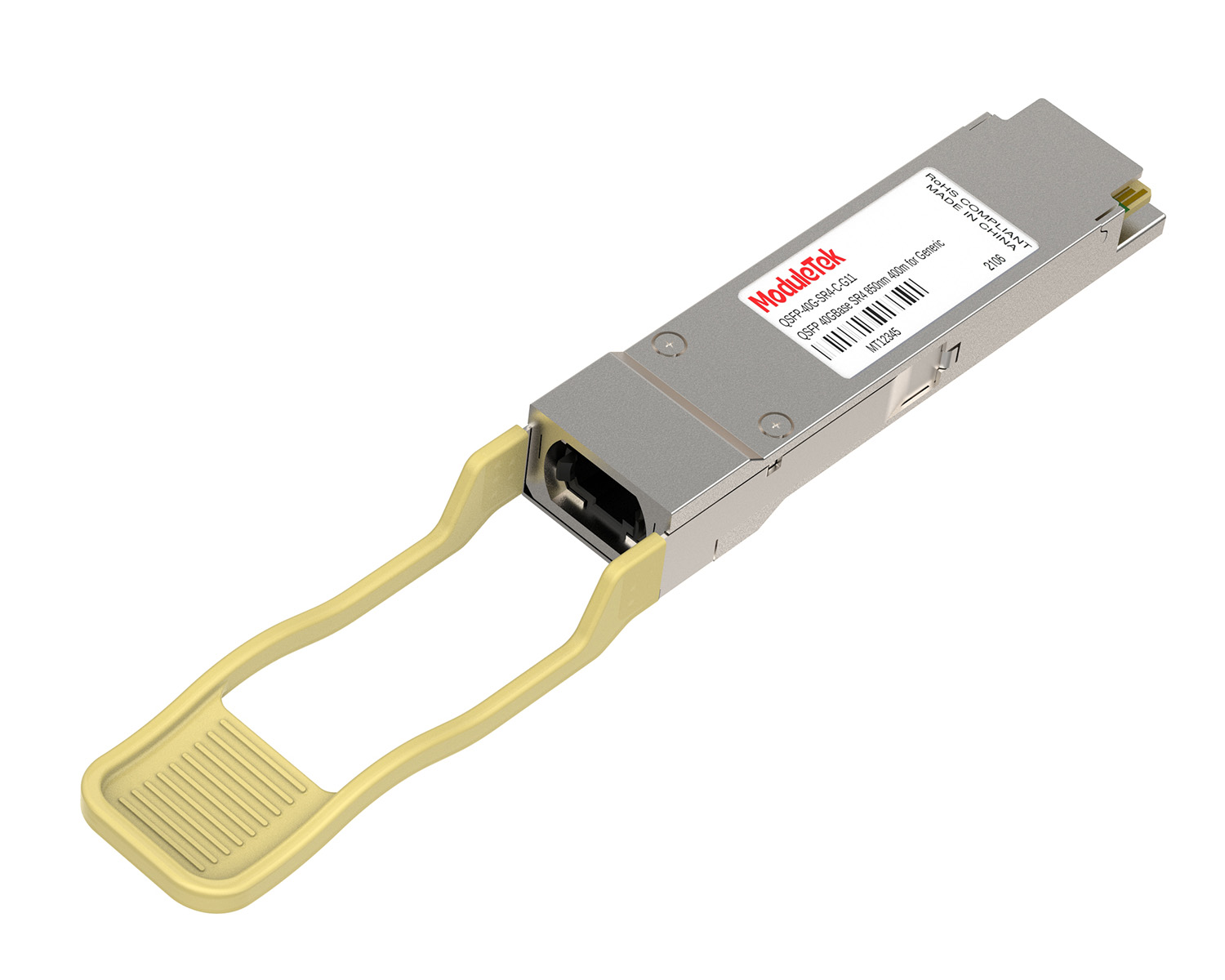
 40G/100G Optical Transceivers
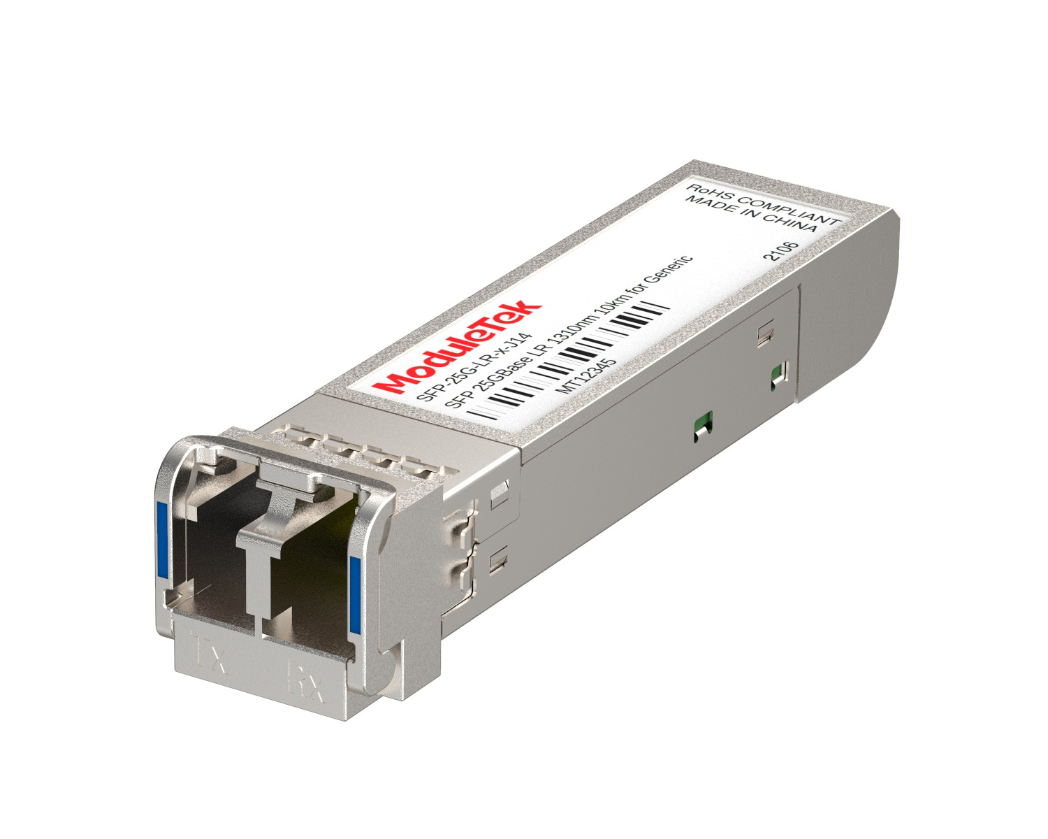 25G Optical Transceivers
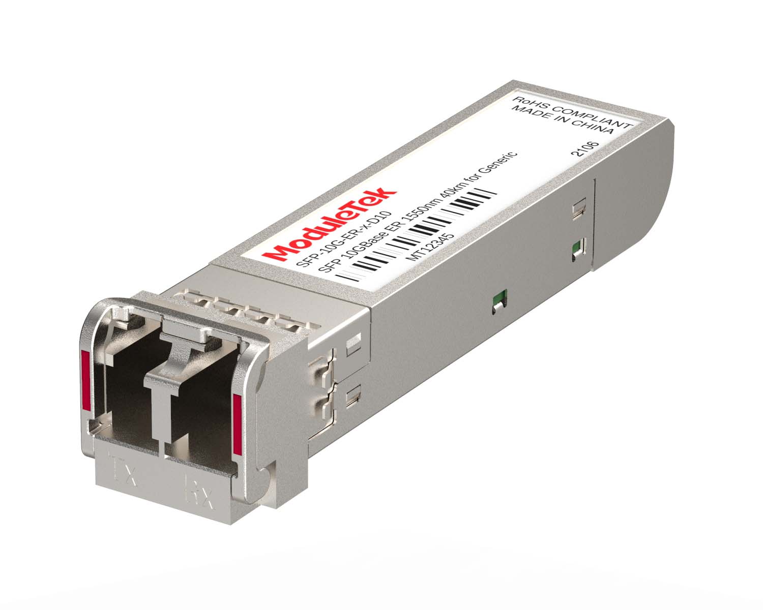 10G Optical Transceivers
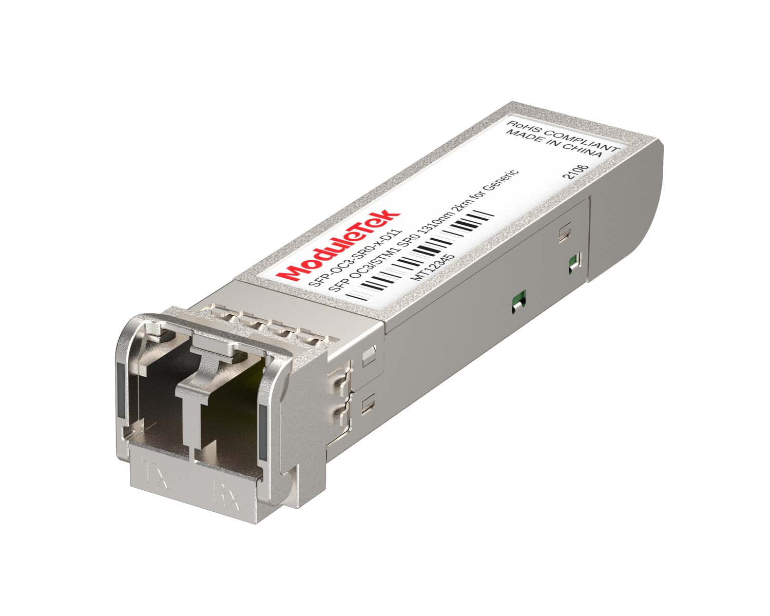 155M/2.5G Optical Transceivers
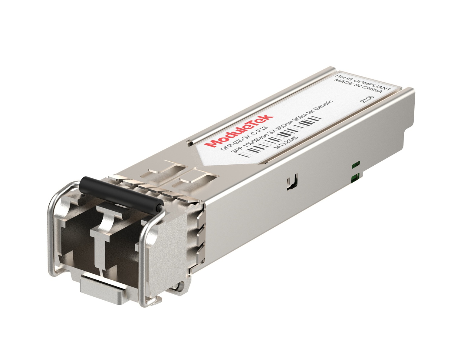 1G Optical Transceivers
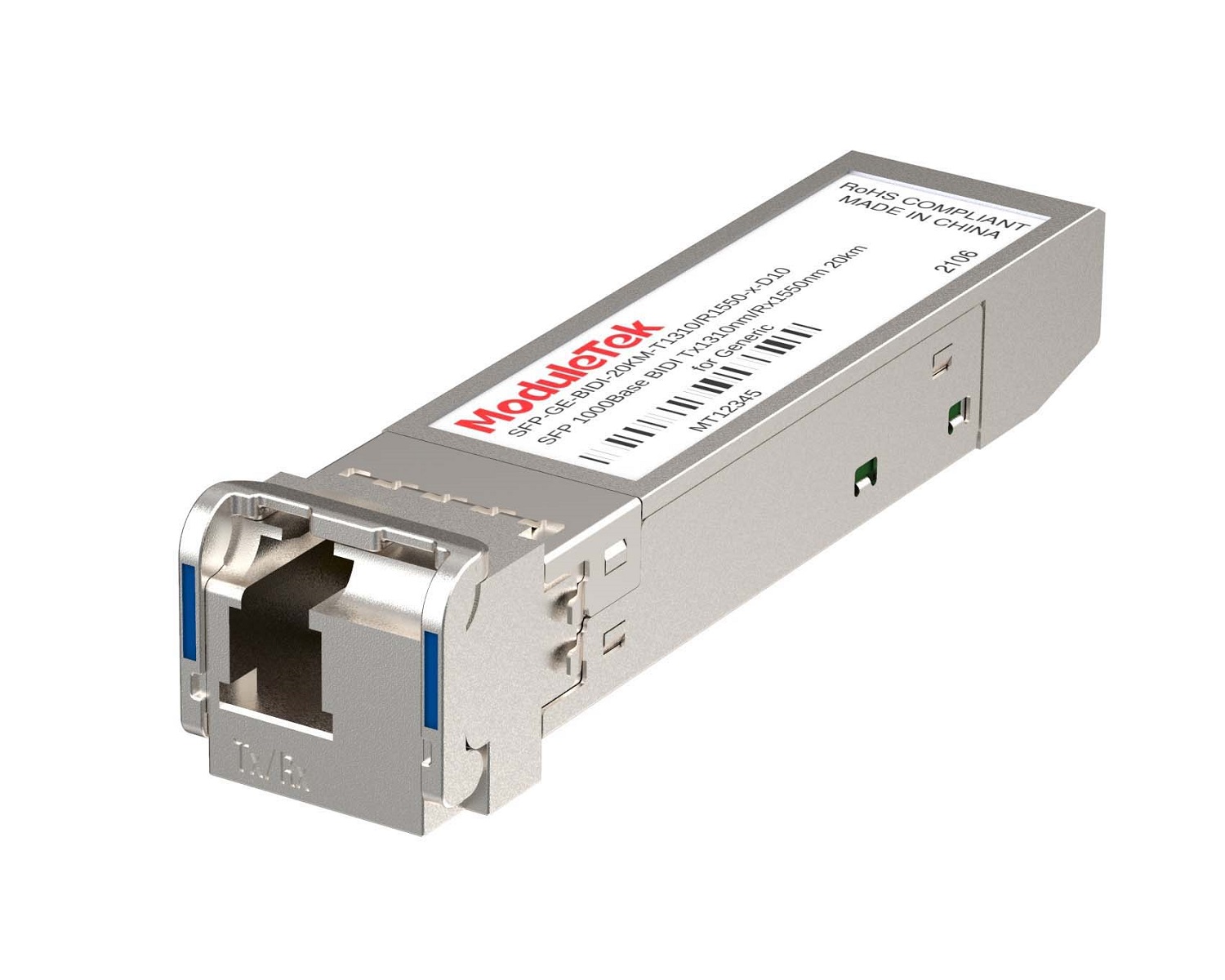 1G BIDI Optical Transceivers
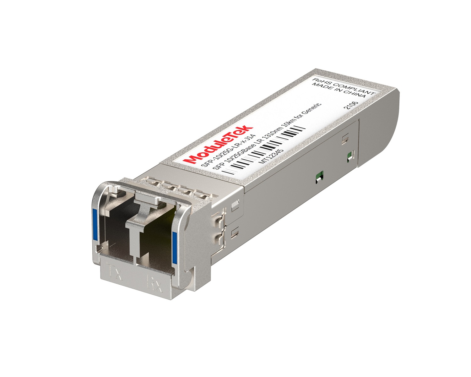 Dual-Rate Optical Transceivers
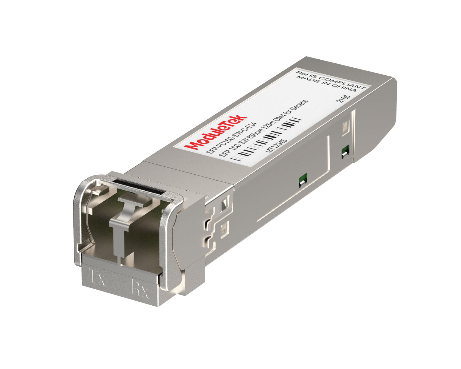 FC 16G/32G Optical Transceivers
 CWDM Optical Transceivers
 DWDM Optical Transceivers
 SGMII Port Optical Transceivers
 XFP Optical Transceivers
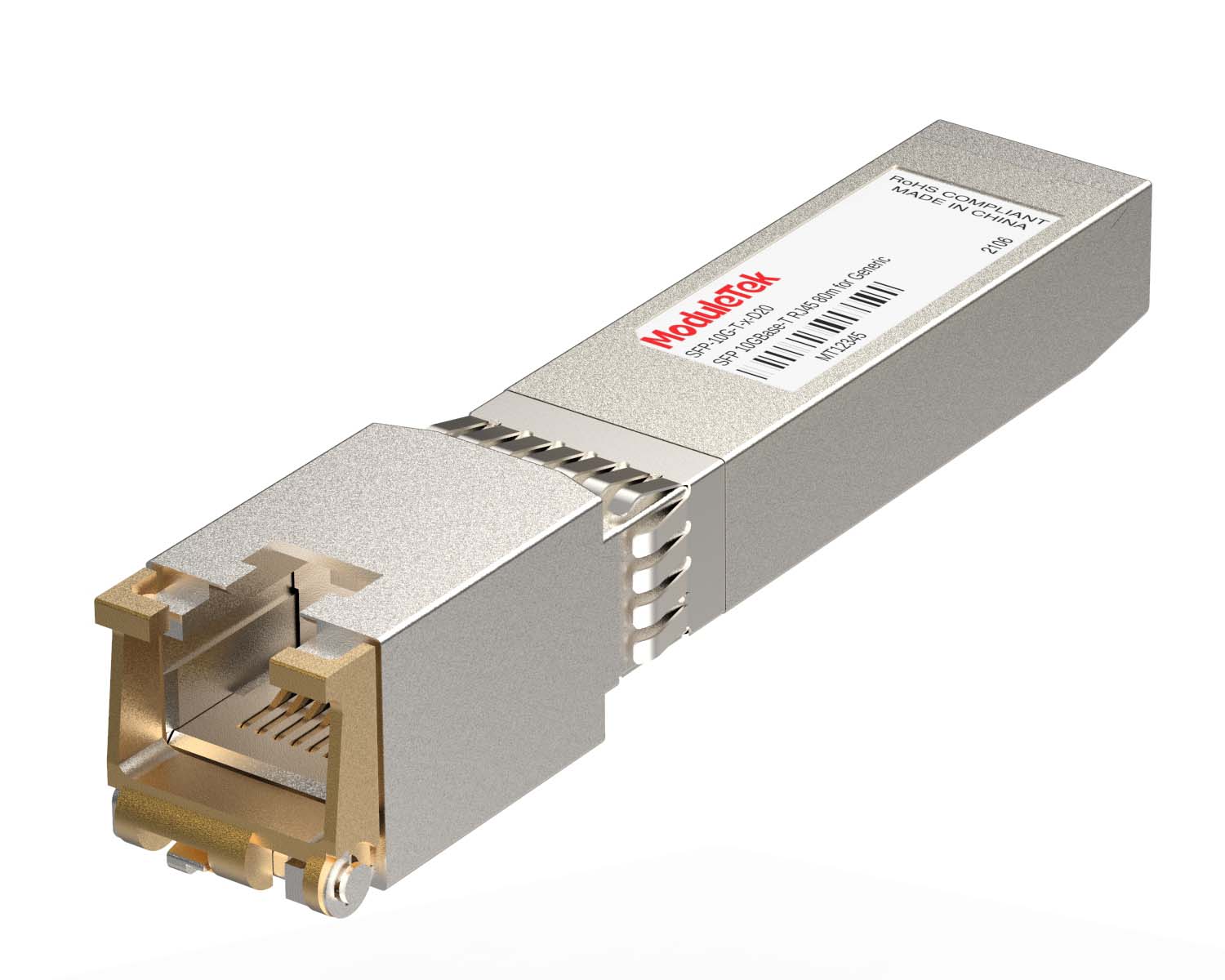 100M/1G/10G Coppers
 Full-Rate AOC & Breakout Series
 10G/40G Active DAC Series
 Full-Rate Passive DAC Series
 40G/100G Passive Breakout DAC Series
 Regular/MTP-MPO Fiber Patch Cords
 MT2011
 MT2010
 CodingBox
 QSFP to SFP Adapter
 首页 > Home > Application Notes > Introducing The 88X3310 Program-Based 10GbE SFP Module Compatible With Multi-Rate Compatibility
Introducing The 88X3310 Program-Based 10GbE SFP Module Compatible With Multi-Rate Compatibility
Time: 2023-06-26
This article introduces the rate compatibility of the host interface and network cable interface for the 10GbE SFP module based on the Marvell 88X3310 solution.
1. Host Interface
The host interface of the 88X3310-based 10GbE SFP module is configured in 10G XFI mode and does not support rate adaptation. Therefore, the module’s 10GbE interface can only be used on switch ports pre-configured to 10G rate; otherwise, it will not function properly.
2. Network Cable Interface
When the 88X3310-based 10GbE SFP module is interconnected (via its RJ45 port) with another module, it supports multi-rate compatibility (10/100/1000 Mbps, 2.5G/5G/10G) and automatically adjusts its rate to match the peer port’s rate.
• If the peer port is fixed at 10G, the module adapts to 10G; if fixed at 1G, it adapts to 1G (and so on for other fixed rates).
• If the peer port supports multi-rate adaptation, the module will negotiate to the highest achievable rate for both ends.
This flexibility allows the module to be used in a variety of Ethernet environments.
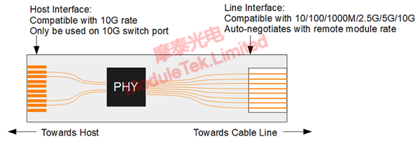
Figure 1 Block Diagram of the Marvell 88X3310 Solution with Multi-Rate Compatibility
The network cable interface supports the following rates and transmission distances:
▪ 10GBase-T (10G) rate: Up to 30 meters over Cat 6A cable.
▪ 5GBase-T rate: Up to 70 meters over Cat 5E cable.
▪ 2.5GBase-T rate: Up to 100 meters over Cat 5E cable.
▪ 10/100/1000Base-T rates: Up to 100 meters over Cat 5E cable.
3. Flow Control
When the 88X3310 solution’s 10GbE interface operates at 10G rate, both the chip’s host side and cable side run at 10G. This eliminates the need for rate conversion and avoids flow control issues.
When the cable side adapts to a rate of 10G or lower, the host side still operates at 10G, resulting in a rate mismatch between the two sides of the chip. The chip therefore requires internal rate conversion. We take the 2.5G rate as an example to illustrate how the chip implements flow control.
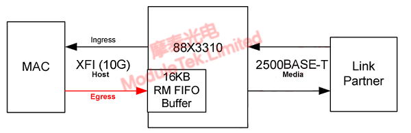
Figure 2 Block Diagram of Flow Control for the 88X3310 Solution
As shown in the figure above:
• Receive Direction: The 88X3310 chip receives data from the peer at 2.5G and transmits it to the host MAC at 10G. Since the receive rate is much lower than the transmit rate, there is no frame overflow, and no flow control is required.
• Transmit Direction: The host MAC sends data to the 88X3310 at 10G, and the chip transmits it to the peer at 2.5G. Without flow control, frame overflow will occur during this process. To prevent this, the 88X3310 enables an internal 16KB FIFO buffer. However, since the receive rate (10G) is much higher than the transmit rate (2.5G), the FIFO buffer will quickly fill up and overflow.
To avoid overflow, the host MAC must insert a specific number of blank frames into the transmitted data. When the 88X3310 receives these blank frames, it discards them and stores only the useful frames in the buffer. When the number of blank frames inserted is appropriate, smooth data transmission is ensured. The exact number of blank frames depends on the wire-side rate and frame length; refer to the 88X3310 datasheet for specific details.
In practice, if the host MAC does not insert the required number of blank frames (as specified in the 88X3310 datasheet), buffer overflow will occur, leading to reduced transmission efficiency. This is manifested by a network link rate of 2.5G but an actual measured bandwidth lower than 2.5G.
Moduletek's 10GbE SFP module based on the 88X3310 solution is an industry-first product. Welcome to purchase! For further inquiries about the above content, please contact us at: sales@moduletek.com