 40G/100G Optical Transceivers
 25G Optical Transceivers
 10G Optical Transceivers
 155M/2.5G Optical Transceivers
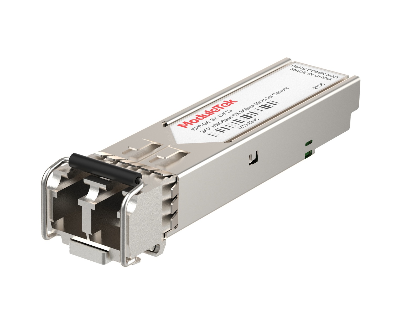 1G Optical Transceivers
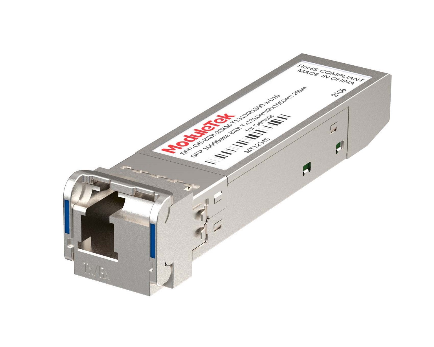 1G BIDI Optical Transceivers
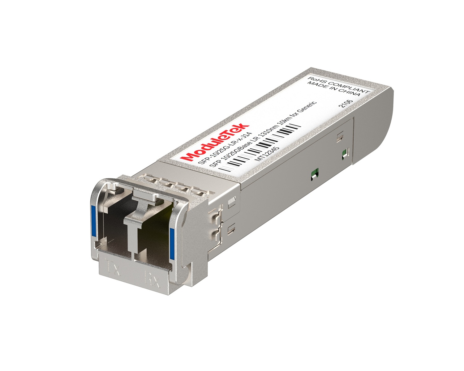 Dual-Rate Optical Transceivers
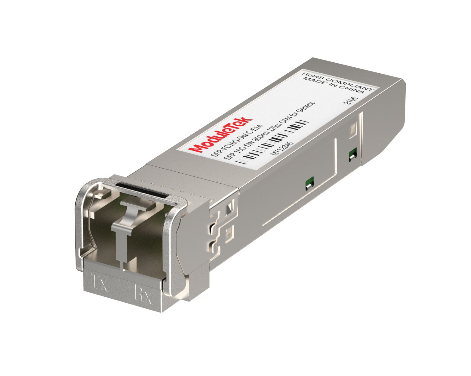 FC 16G/32G Optical Transceivers
 CWDM Optical Transceivers
 DWDM Optical Transceivers
 SGMII Port Optical Transceivers
 XFP Optical Transceivers
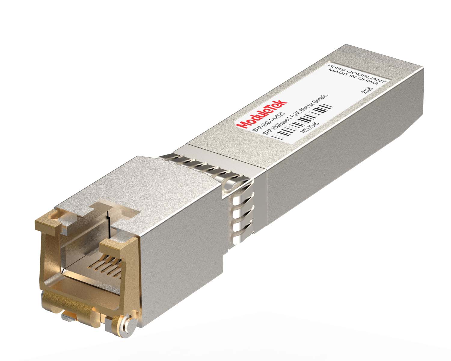 100M/1G/10G Coppers
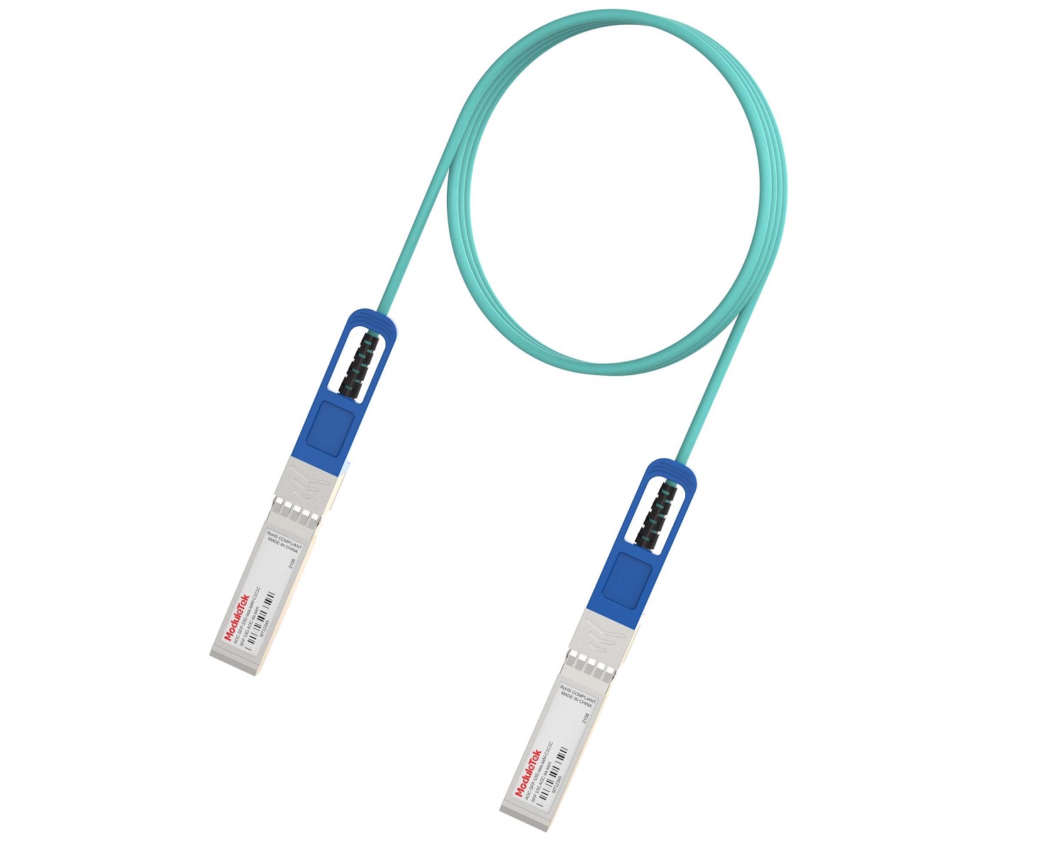 Full-Rate AOC & Breakout Series
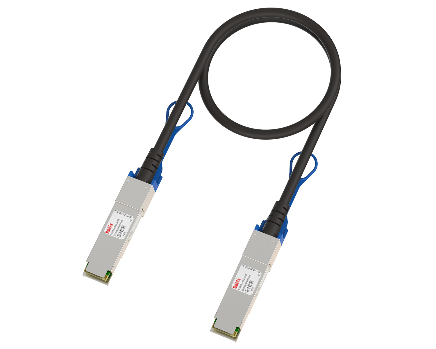 10G/40G Active DAC Series
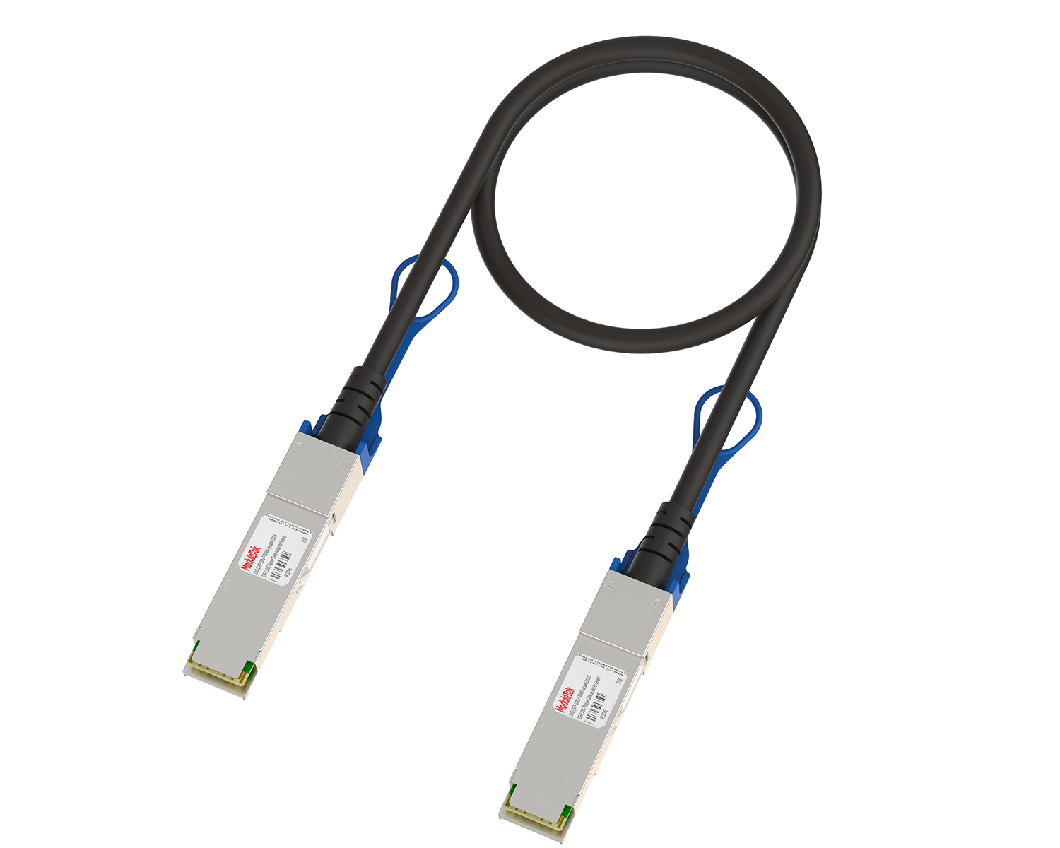 Full-Rate Passive DAC Series
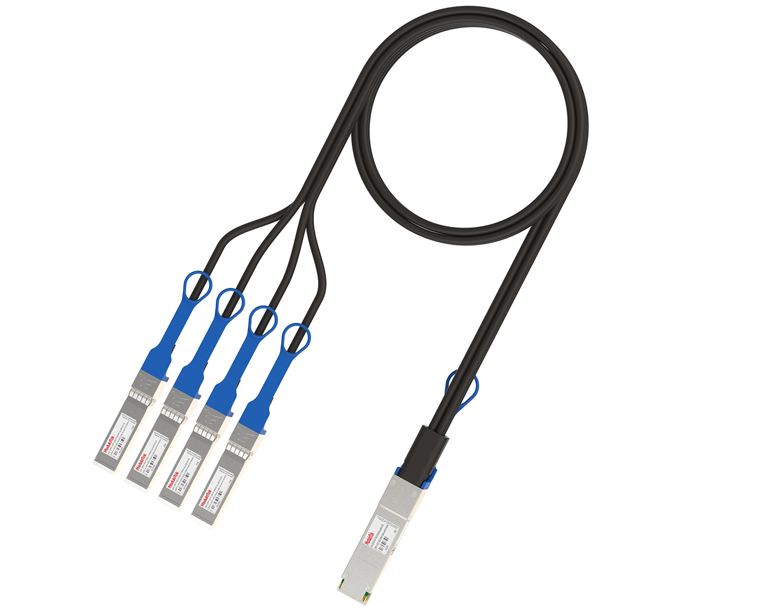 40G/100G Passive Breakout DAC Series
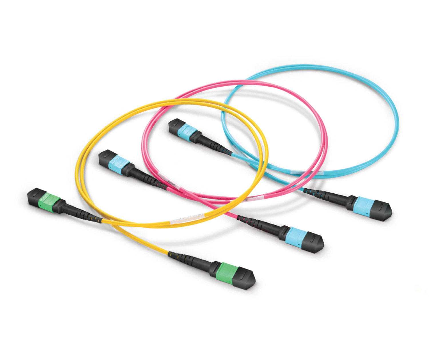 Regular/MTP-MPO Fiber Patch Cords
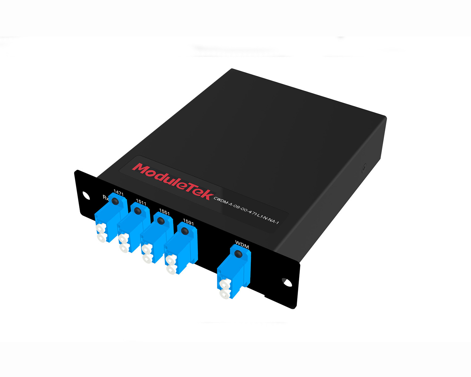 MT2011
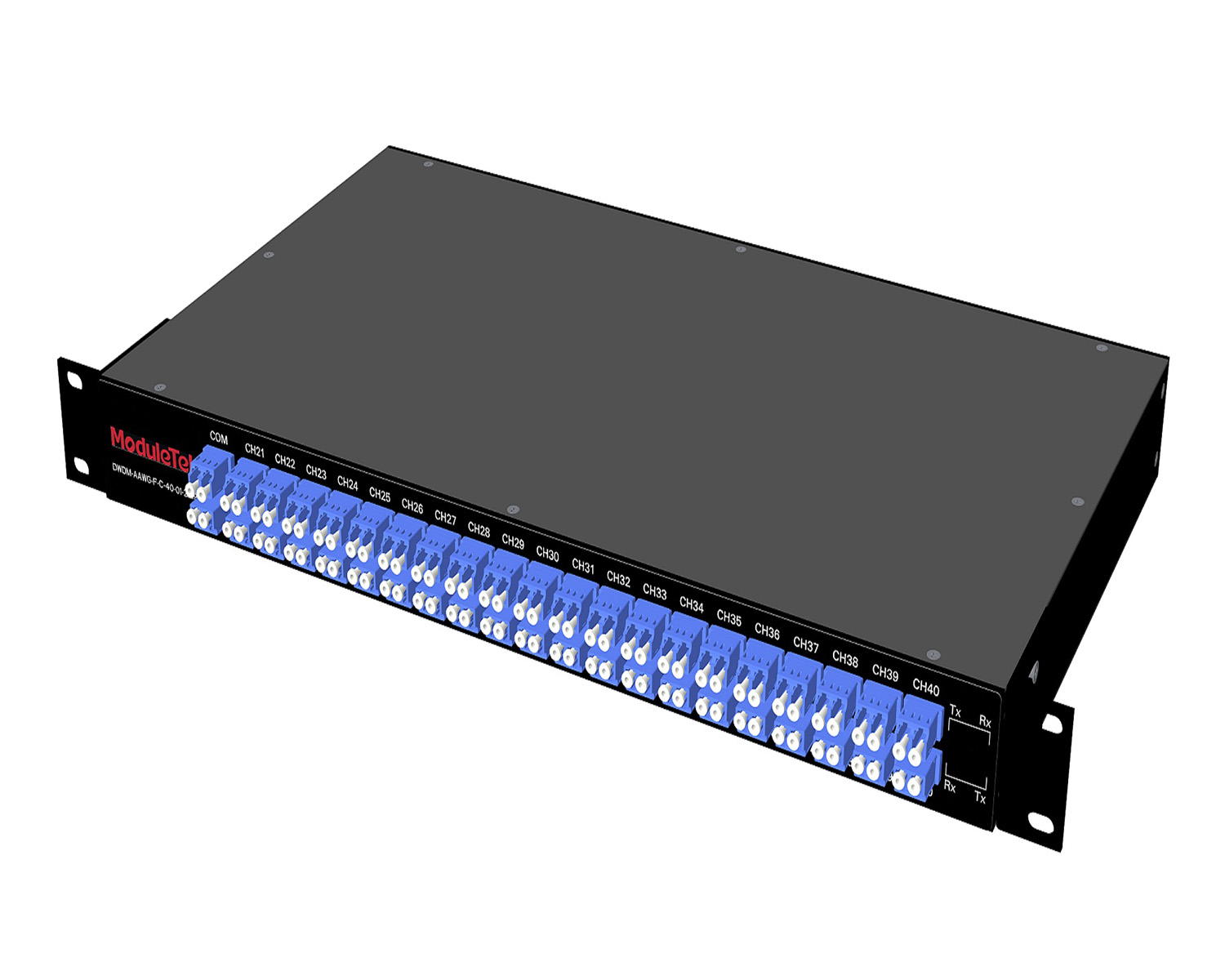 MT2010
 CodingBox
 QSFP to SFP Adapter
How To Configure Switch Interface FEC Mode
Time: 2023-07-11
FEC (Forward Error Correction) is an error correction mechanism that improves signal quality and reduces BER (Bit Error Rate).
It adds error-correction bits to data packets at the transmit end, which the receive end uses to correct bit errors during transmission.
This function introduces slight signal latency, so you can enable or disable it based on actual network requirements.
FEC is widely used in high-speed optical module communications such as 25G and 100G.
This document uses a Moduletek SFP-10/25G-CSR optical module connected to a Cisco C9300 switch as an example to explain how to configure interface FEC mode.
1. FEC Mode Configuration
Enter interface configuration mode and run the following command to view supported FEC options:
fec ?
Available FEC modes vary by switch model. Configure the required FEC mode according to your network plan.
2. View Interface FEC Mode
Run the following command to check the current FEC configuration of the interface:
show interface <interface-type> <interface-number>
The output will display the FEC mode currently in use.
Important Notes:
1. Different switch models and module types use different default FEC modes.
2. FEC participates in link auto-negotiation.
FEC must be enabled or disabled on both ends of the link, and the FEC mode must be identical at both sides; otherwise, the interface will not go Up.
Moduletek provides high-speed optical modules supporting various FEC modes. Welcome to purchase!
For further inquiries about the above content, please contact us at: sales@moduletek.com


