 40G/100G Optical Transceivers
 25G Optical Transceivers
 10G Optical Transceivers
 155M/2.5G Optical Transceivers
 1G Optical Transceivers
 1G BIDI Optical Transceivers
 Dual-Rate Optical Transceivers
 FC 16G/32G Optical Transceivers
 CWDM Optical Transceivers
 DWDM Optical Transceivers
 SGMII Port Optical Transceivers
 XFP Optical Transceivers
 100M/1G/10G Coppers
 Full-Rate AOC & Breakout Series
 10G/40G Active DAC Series
 Full-Rate Passive DAC Series
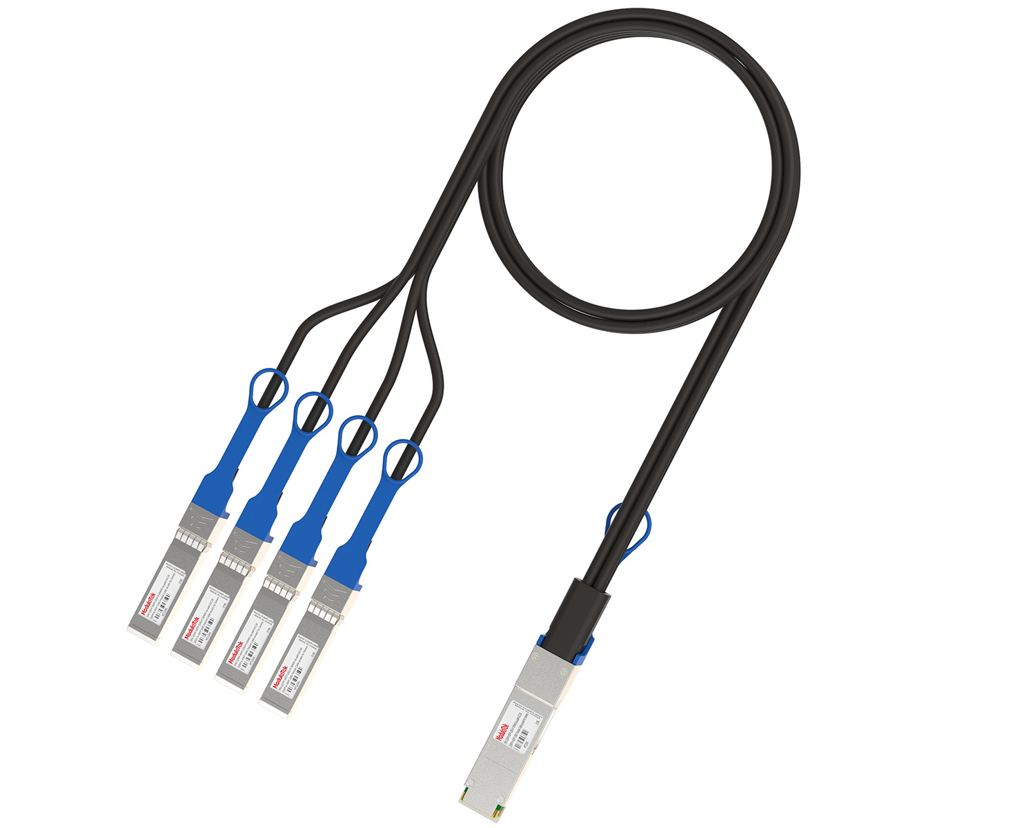 40G/100G Passive Breakout DAC Series
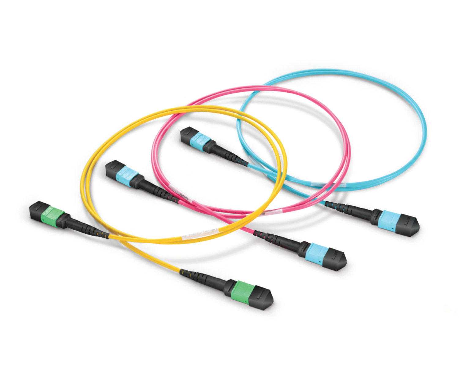 Regular/MTP-MPO Fiber Patch Cords
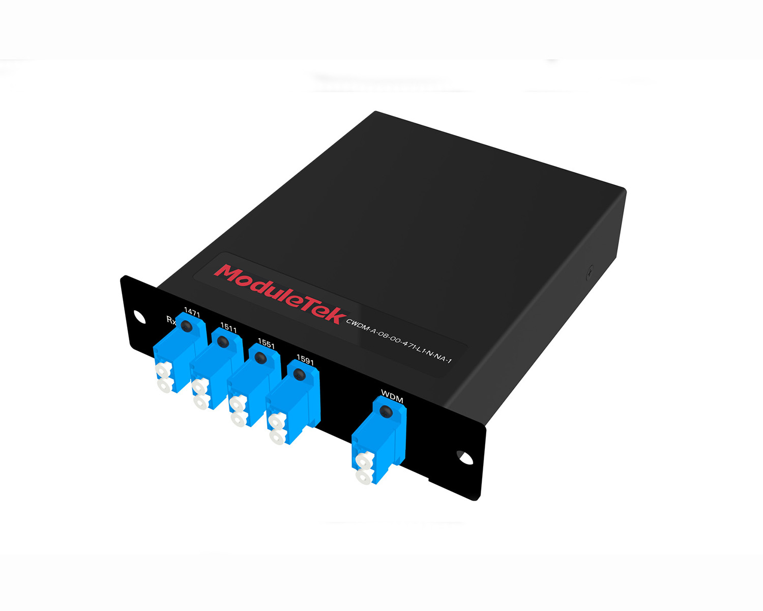 MT2011
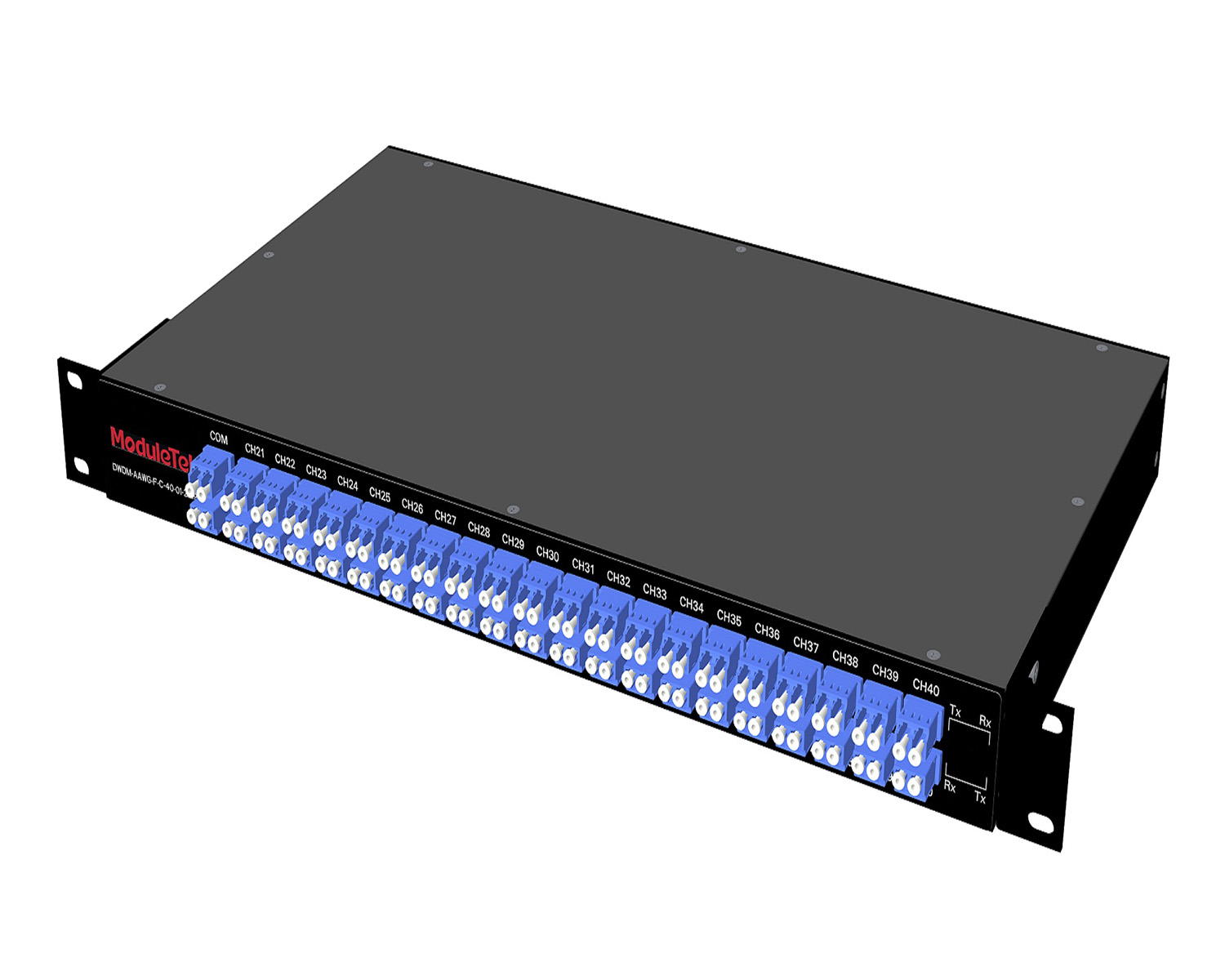 MT2010
 CodingBox
 QSFP to SFP Adapter
Structure Of TFF WDM Passive Components
Time: 2023-12-01
Filter-type Wavelength Division Multiplexer, referred to as Filter WDM, is also known as the TFF-type 3-port WDM device because it is constructed using Thin Film Filters (TFF).
It mainly consists of the following parts:
On the left side, a single-fiber pigtail collimator and a C‑Lens are bonded and fixed together, then connected by a glass tube.
On the right side, a waveplate, a G‑Lens, and a dual-fiber pigtail collimator are sequentially bonded and fixed, then enclosed in a glass tube with the same outer diameter as the single-fiber collimator assembly.
Finally, a large glass tube is used to connect the left and right assemblies, forming a standard 3‑port device, as shown in Figure 1 (shaded areas represent adhesive).
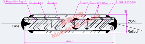
Figure 1 Filter-type Wavelength Division Multiplexer
Detailed Component Introduction
① C‑Lens (Conventional Lens)
The C‑Lens is a thick cylindrical lens with a fixed refractive index. Its light transmission principle is the same as that of an ordinary lens, with uniform refractive index throughout the lens.
However, it differs from conventional lenses in material: it uses a high‑refractive‑index material optimized for the optical communication band, which features excellent acid and alkali corrosion resistance.
One end face of the C‑Lens is spherical, and the other is angled.
When coated with an anti‑reflection (AR) coating on both end faces, it achieves an extremely high transmittance of over 99.9% for wavelengths used in fiber-optic communication.
The mechanical dimensions of the C‑Lens are shown in Figure 2.
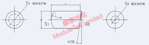
Figure 2 Conventional Lens (C‑Lens)
② G‑Lens (Gradient‑index Lens)
The G‑Lens is a gradient‑index lens, also known as a GRIN lens.
The biggest difference from the conventional C‑Lens is that its refractive index gradually decreases radially from the central axis toward the outer edge.
This allows light traveling along the axis to undergo continuous refraction, enabling smooth and focused beam convergence.
The mechanical dimensions of the G‑Lens are shown in Figure 3.
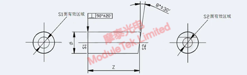
Figure 3 Gradient-index Lens (G‑Lens)
③ Dual-fiber Pigtail Collimator
It serves as the optical input/output carrier and protects the internal fiber.
An AR coating on its 8° angled end face further improves optical transmission performance.
In a TFF WDM device, one fiber acts as the COM (common) input port, and the other acts as the Reflect (reflected) output port.
After the 8° angled end face is coupled with the 8° angled face of the G‑Lens, light entering from the COM port is focused on the axis‑perpendicular face of the G‑Lens.
Based on the specific wavelength coatings on both sides of the filter, two distinct wavelength bands are separated: the reflected wavelength band is output from the Reflect port of the dual-fiber pigtail.
The mechanical dimensions of the dual-fiber pigtail collimator are shown in Figure 4.
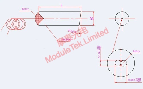
Figure 4 Dual-fiber Pigtail Collimator
④ Single-fiber Pigtail Collimator
It also acts as an optical input/output carrier and provides fiber protection.
Coupled with the C‑Lens, it receives the wavelength band transmitted through the filter from the COM port of the dual-fiber pigtail, with an output port labeled Pass (transmitted).
The mechanical dimensions of the single-fiber pigtail collimator are shown in Figure 5.
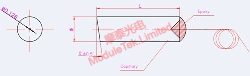
Figure 5 Single-fiber Pigtail Collimator
⑤ Glass Tube
Glass tubes are mainly used for fixing, connecting, and maintaining stable internal optical paths:
• Glass Tube ①: Short tube used at the dual-fiber collimator for sealing and fixing, ensuring a consistent outer diameter with the single-fiber collimator.
• Glass Tube ②: Fixes the single-fiber pigtail and covers the adhesive joint between the C‑Lens and the single-fiber collimator.
• Glass Tube ③: Protects and connects the single-fiber and dual-fiber assemblies, ensuring stable and reliable optical paths.
The mechanical dimensions of the glass tubes are shown in Figure 6.
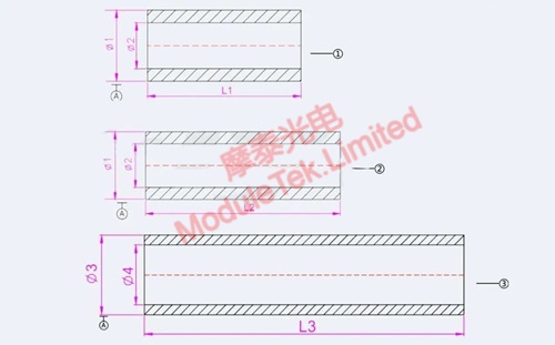
Figure 6 Glass Tube
⑥ Filter
A standard filter is a square crystal with dimensions of 1.4 × 1.4 × 1.0 mm, based on a glass substrate coated with dozens of layers of dielectric films of different materials, refractive indices, and thicknesses.
It uses a periodic structure composed of alternating high‑ and low‑refractive‑index dielectric films to create a passband for a target wavelength range and a stopband for other wavelengths, achieving the desired filtering performance.
Its function is similar to a partial reflective mirror, with a central cavity layer separating two reflectors.
An anti‑reflection coating is also applied to the reverse side of the glass substrate to improve wavelength transmittance.
The coated sides can be distinguished visually: the reflective side usually appears darker, as shown in Figure 7.

Figure 7 Thin Film Filter (TFF)
Moduletek provides a full range of TFF WDM passive WDM products. Welcome to purchase!
For further inquiries about the above content, please contact us at: sales@moduletek.com


