
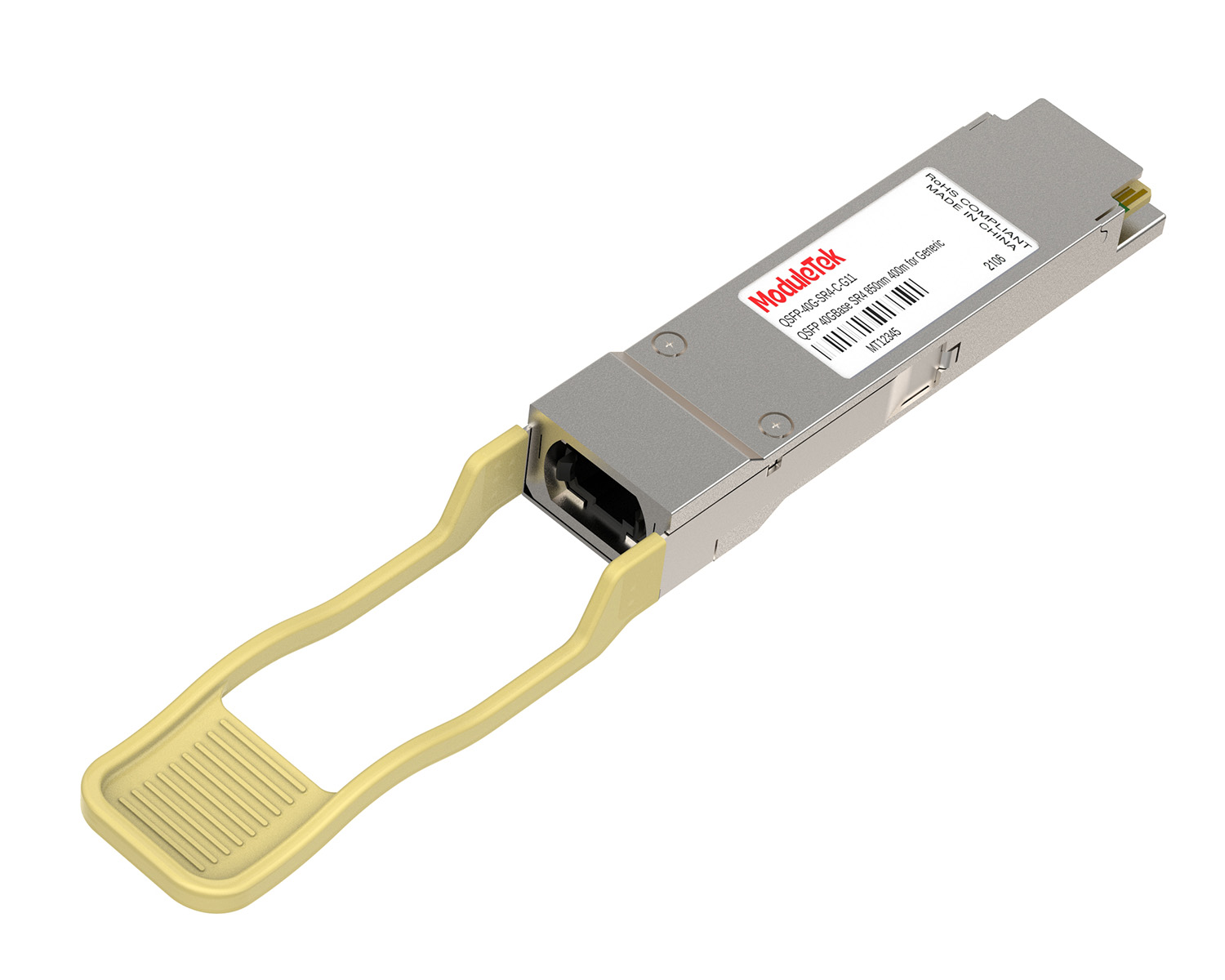
 40G/100G Optical Transceivers
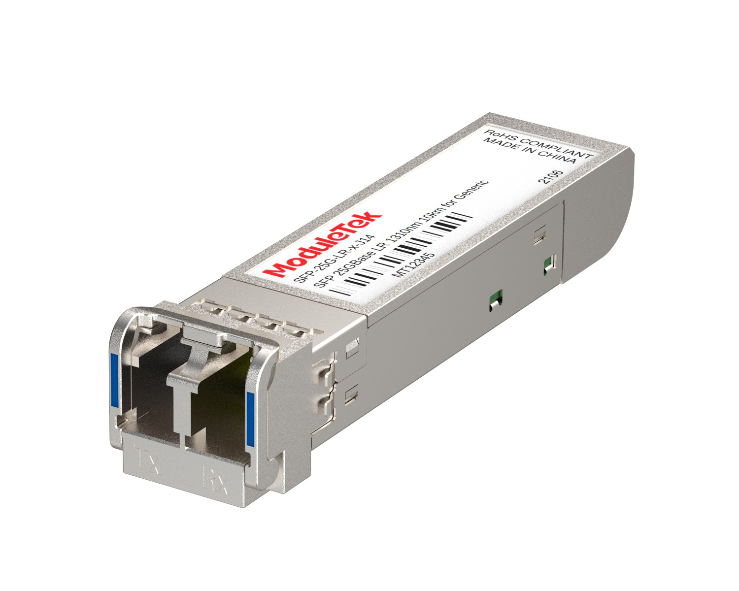 25G Optical Transceivers
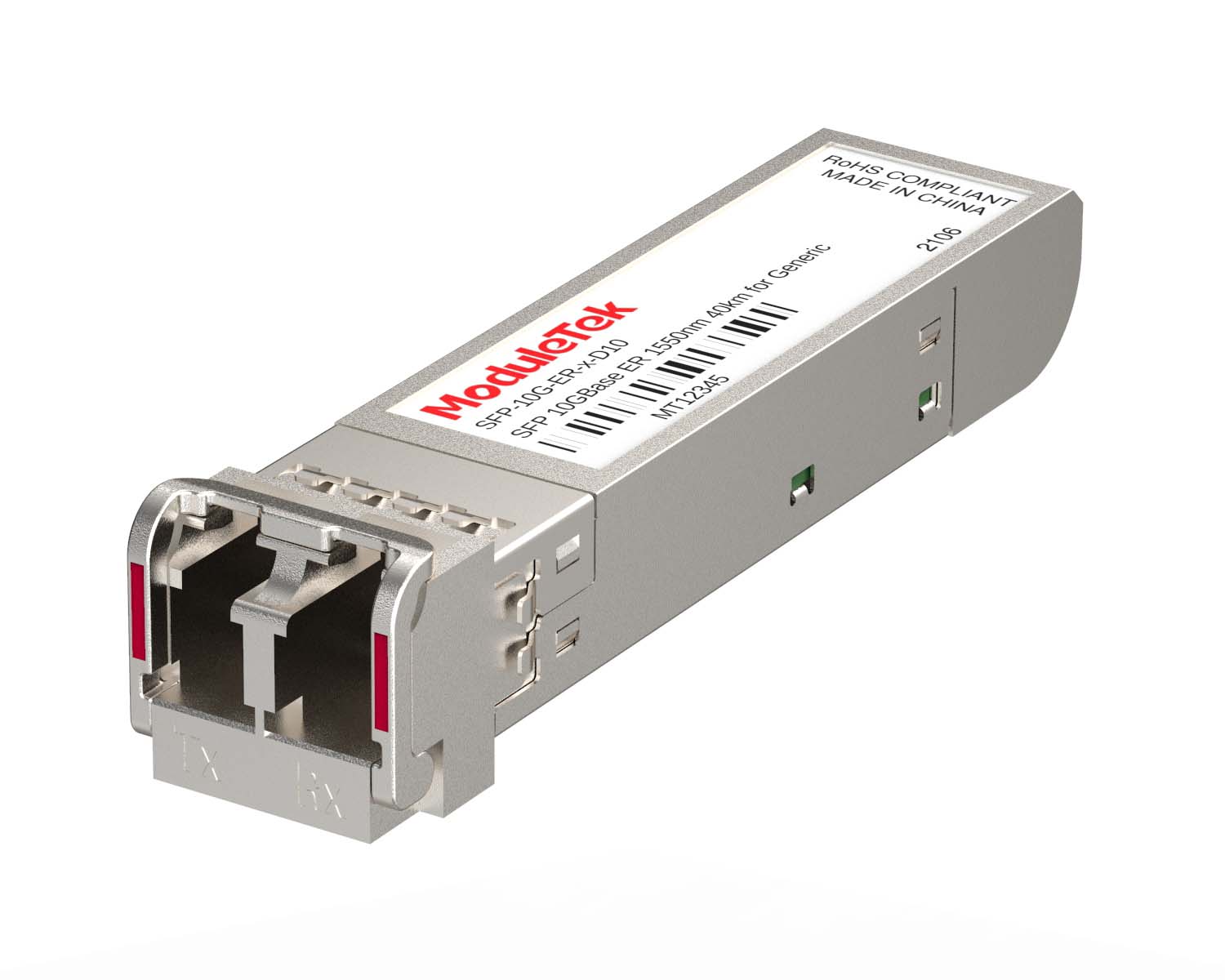 10G Optical Transceivers
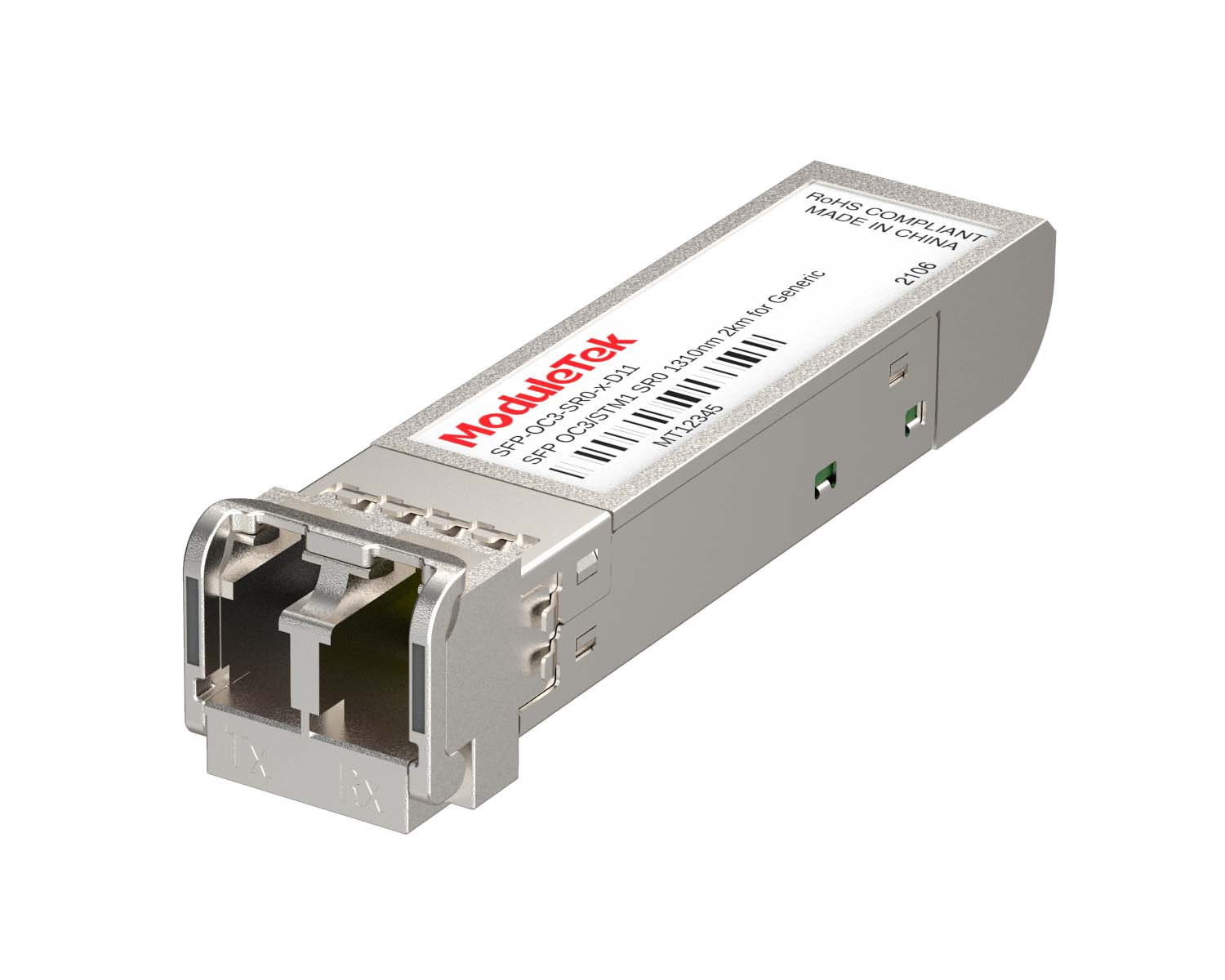 155M/2.5G Optical Transceivers
 1G Optical Transceivers
 1G BIDI Optical Transceivers
 Dual-Rate Optical Transceivers
 FC 16G/32G Optical Transceivers
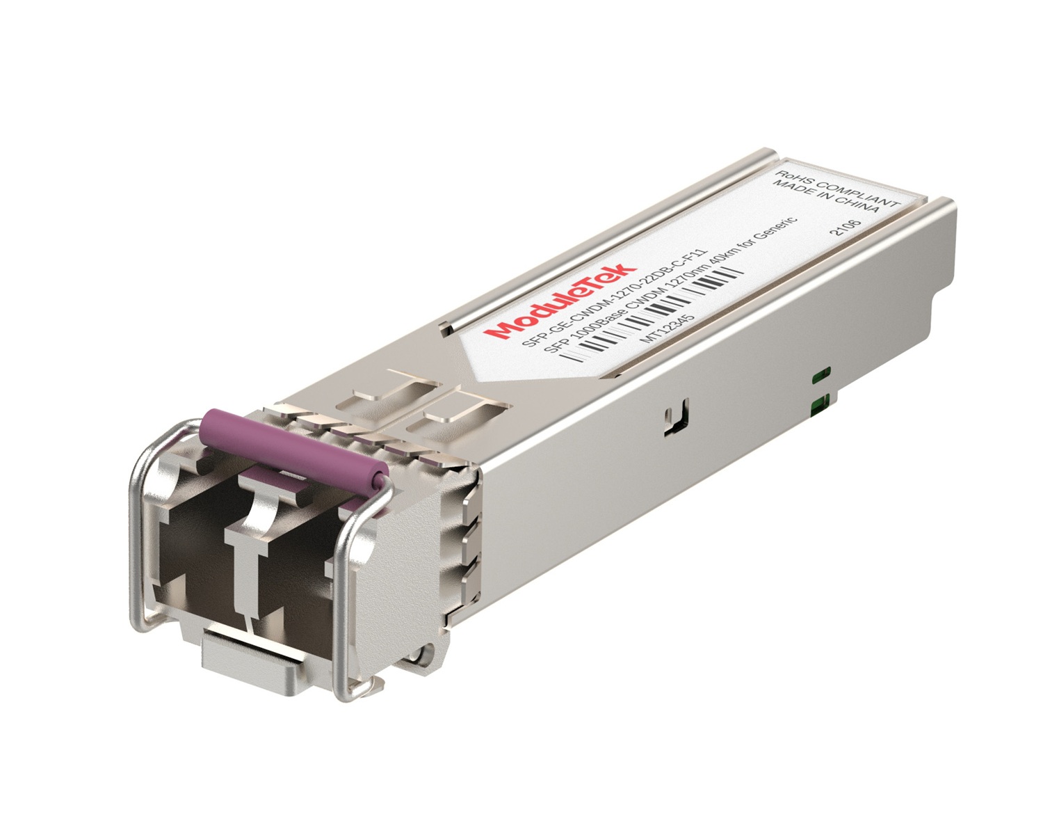 CWDM Optical Transceivers
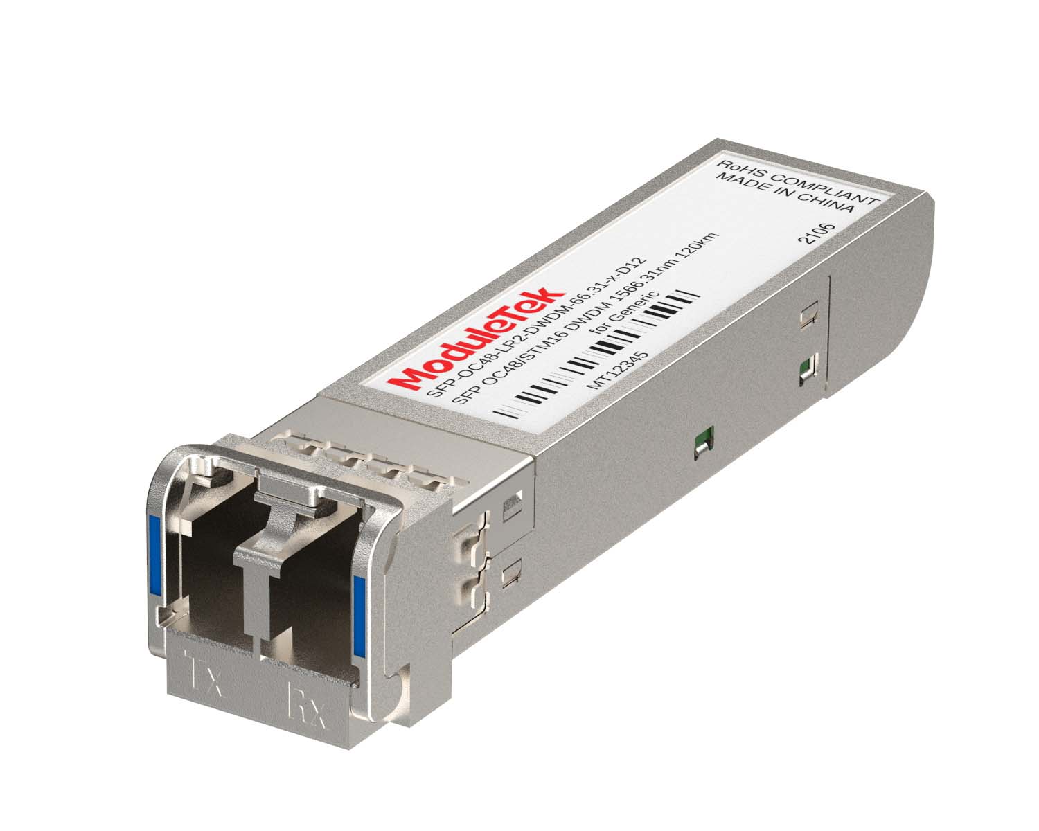 DWDM Optical Transceivers
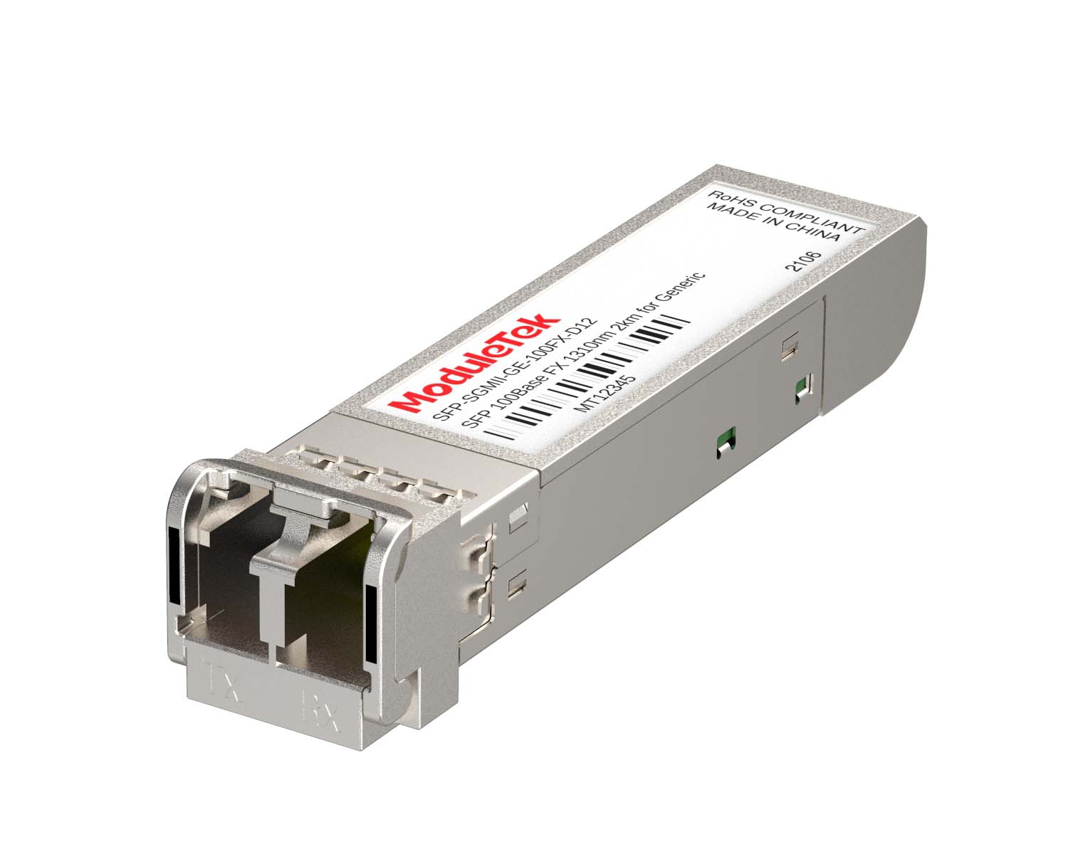 SGMII Port Optical Transceivers
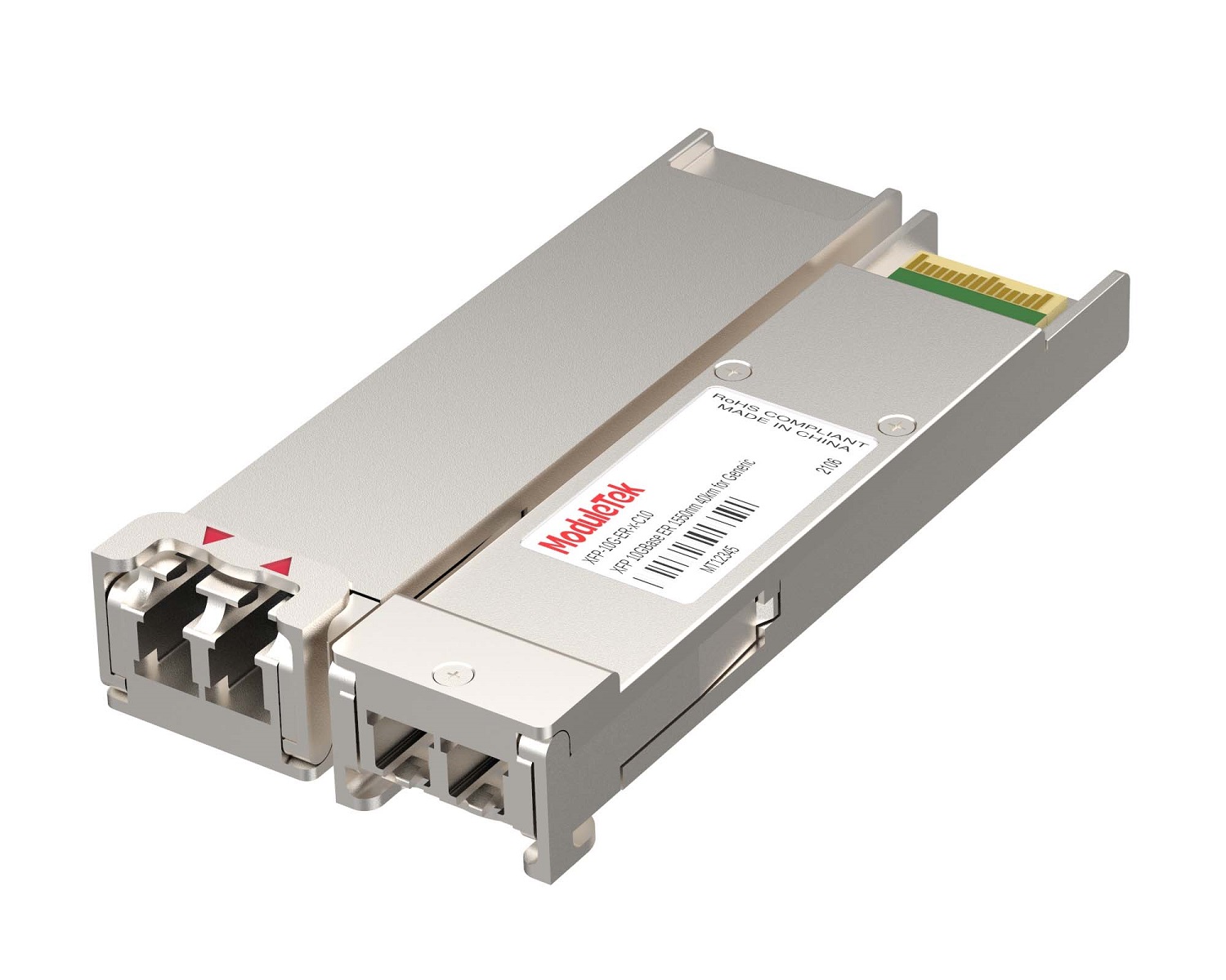 XFP Optical Transceivers
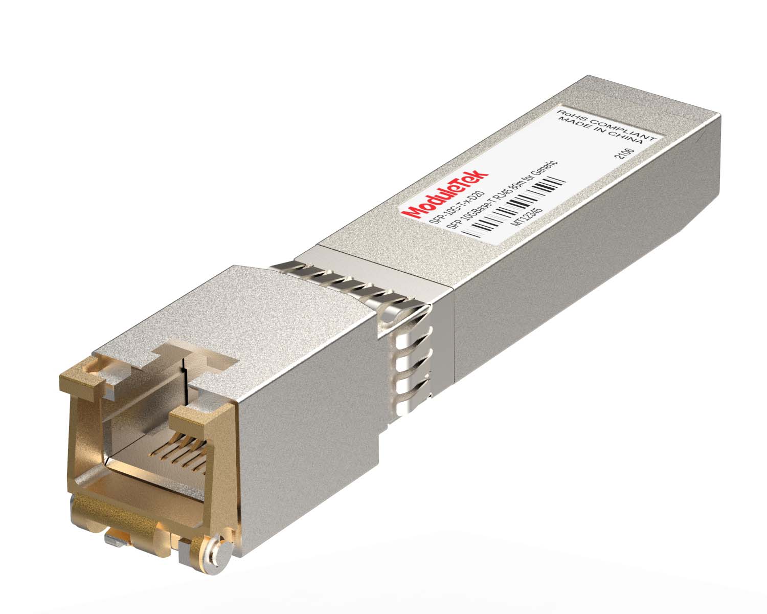 100M/1G/10G Coppers
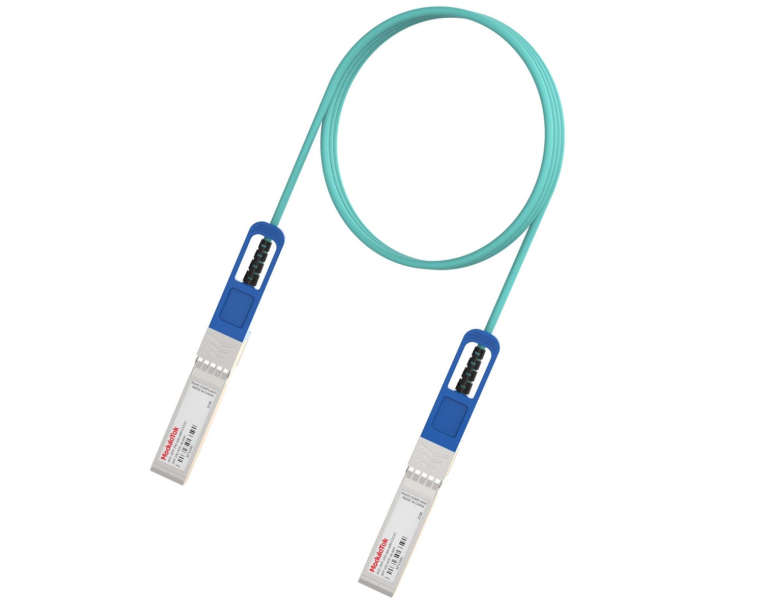 Full-Rate AOC & Breakout Series
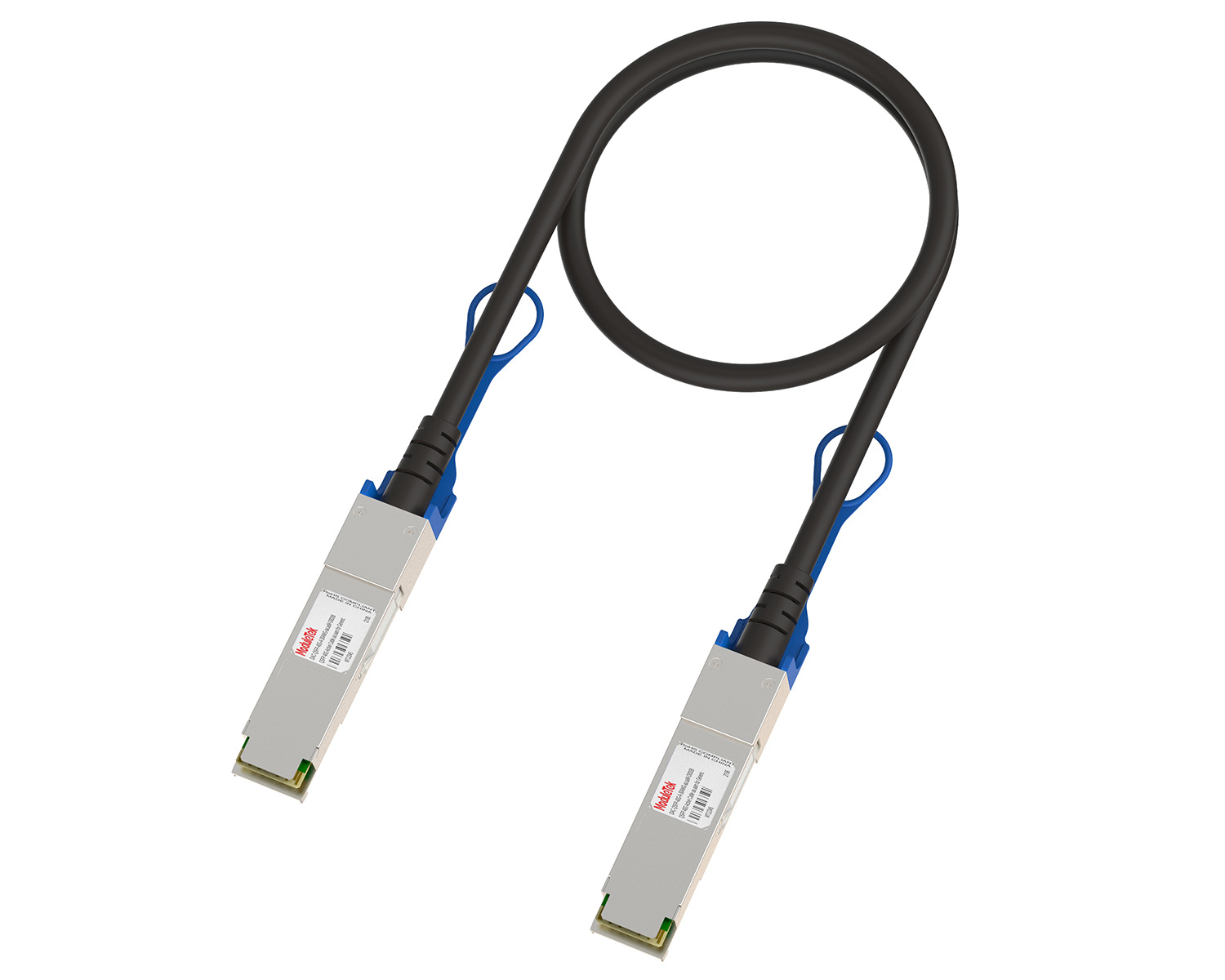 10G/40G Active DAC Series
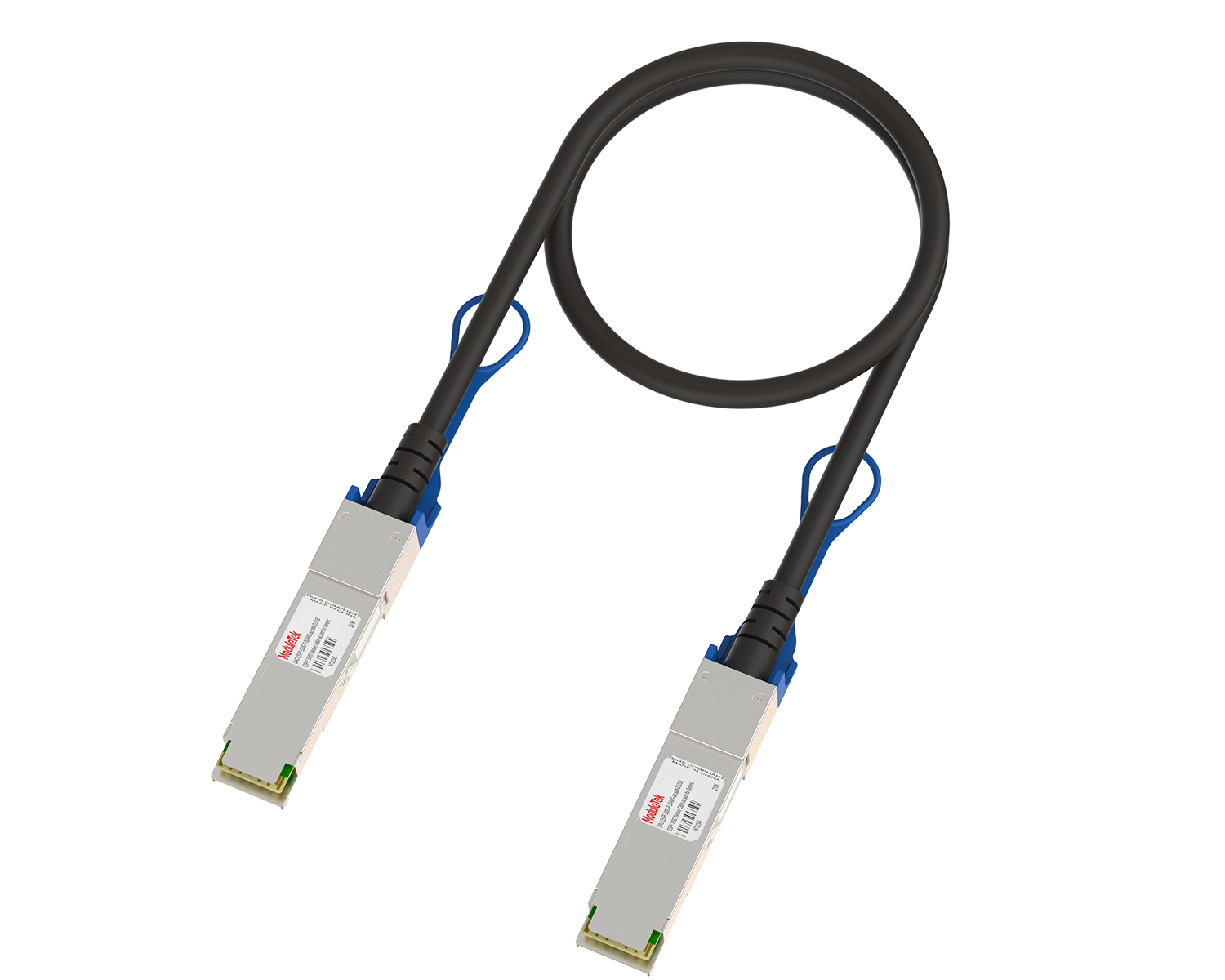 Full-Rate Passive DAC Series
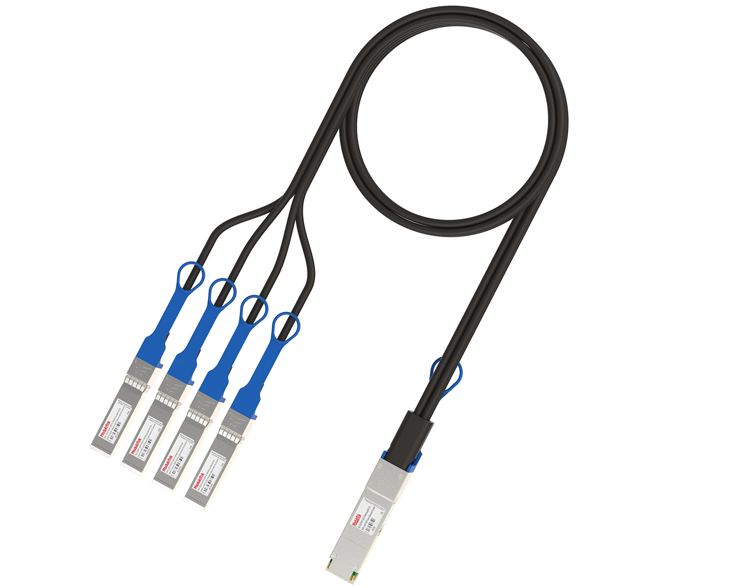 40G/100G Passive Breakout DAC Series
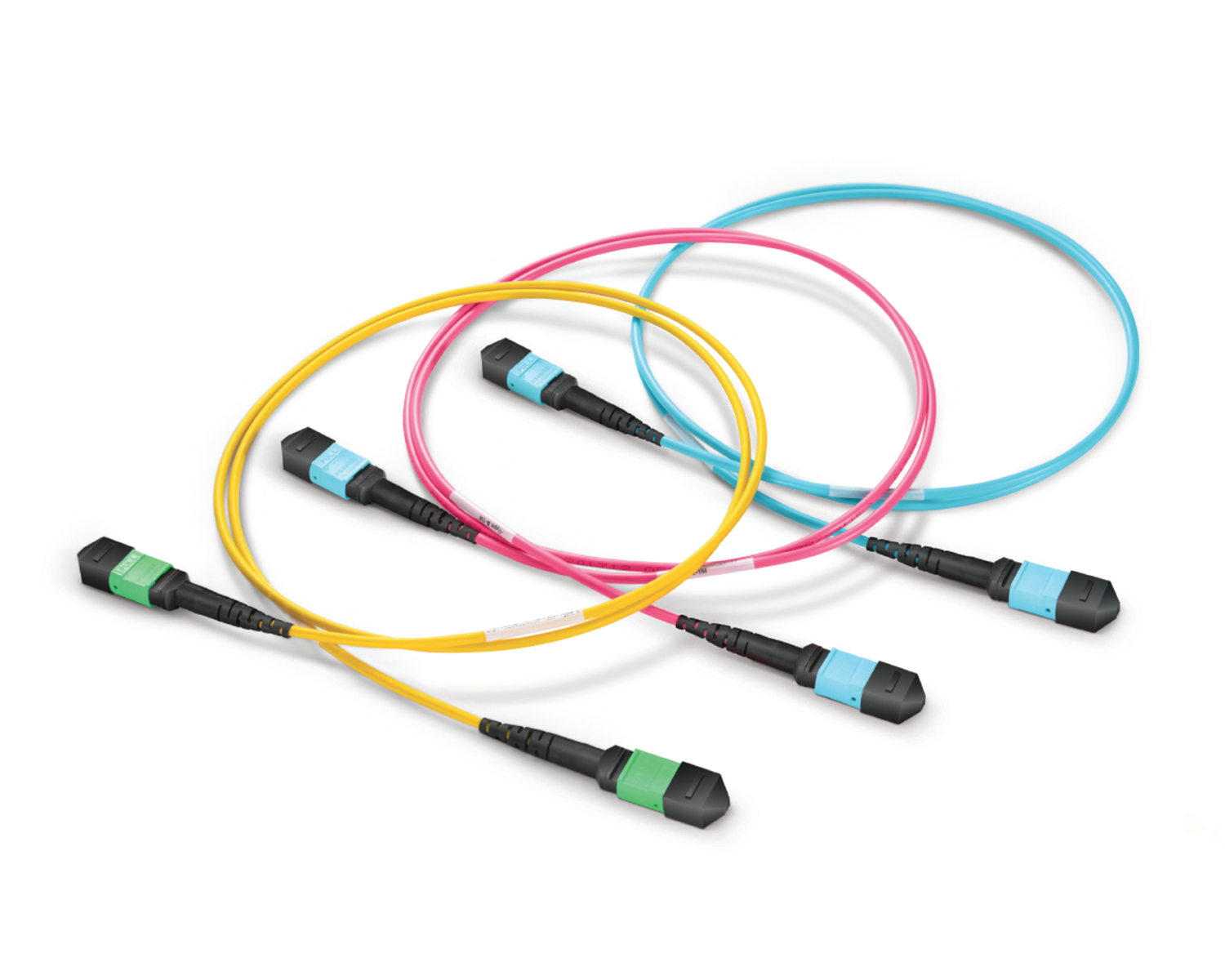 Regular/MTP-MPO Fiber Patch Cords
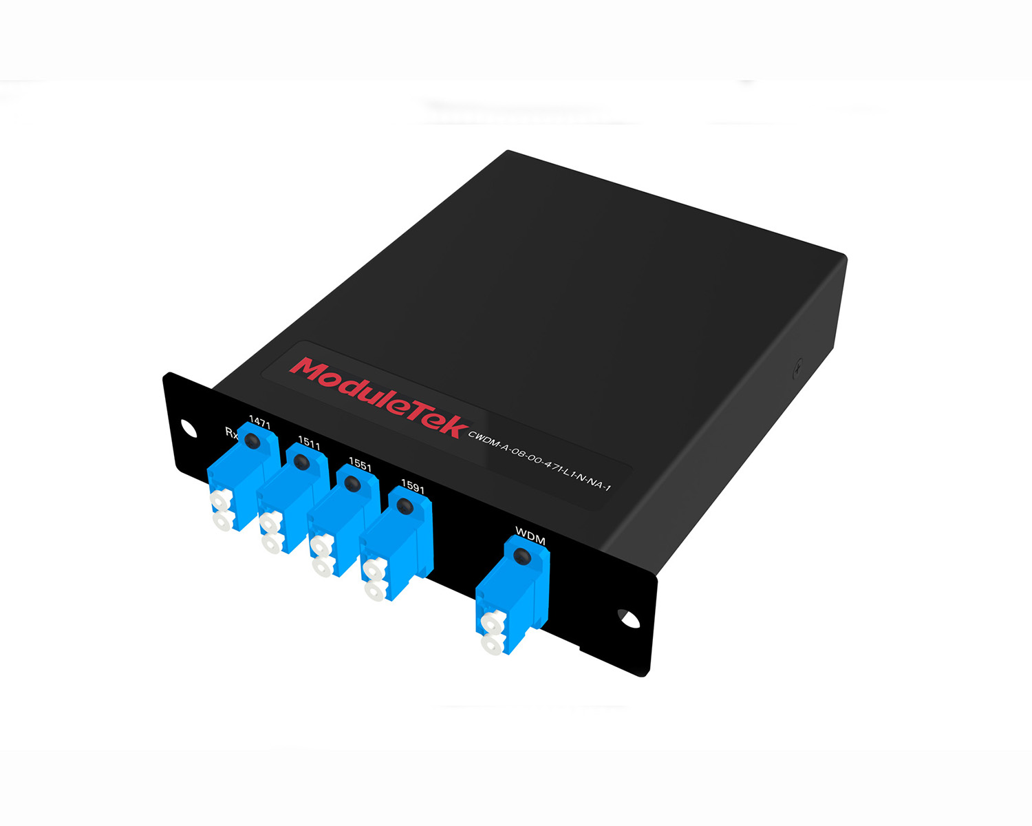 MT2011
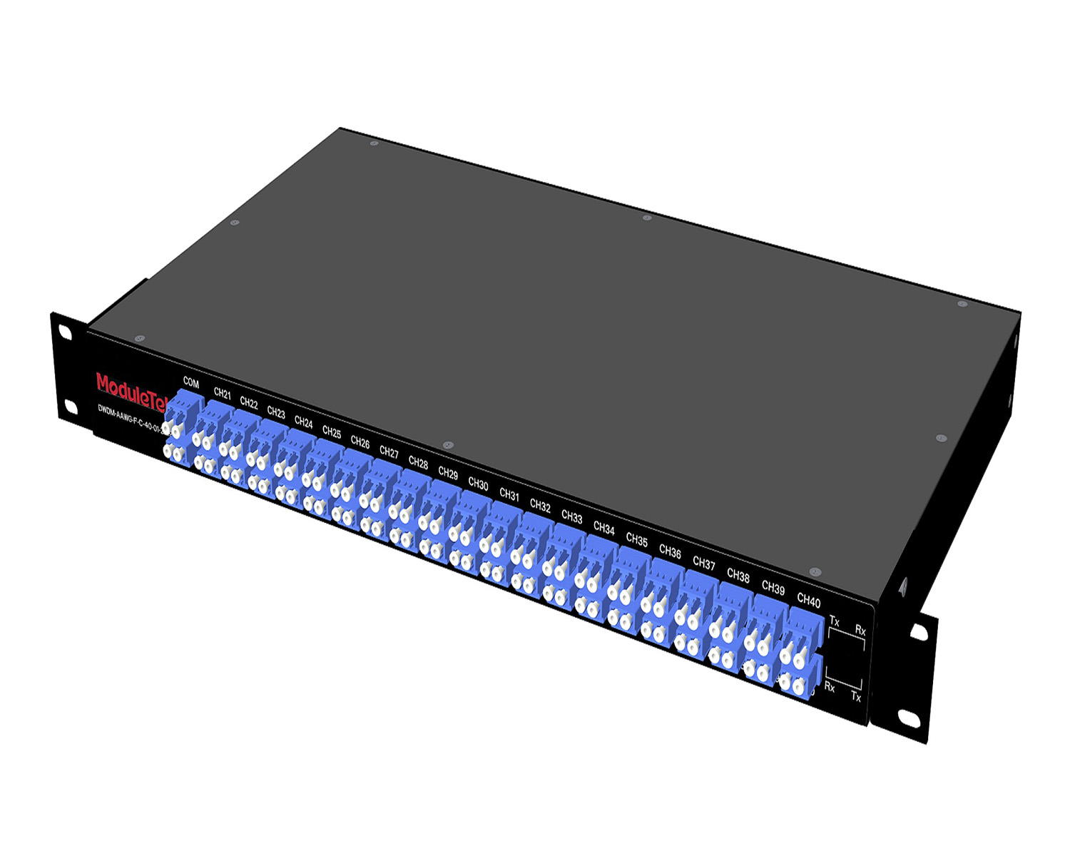 MT2010
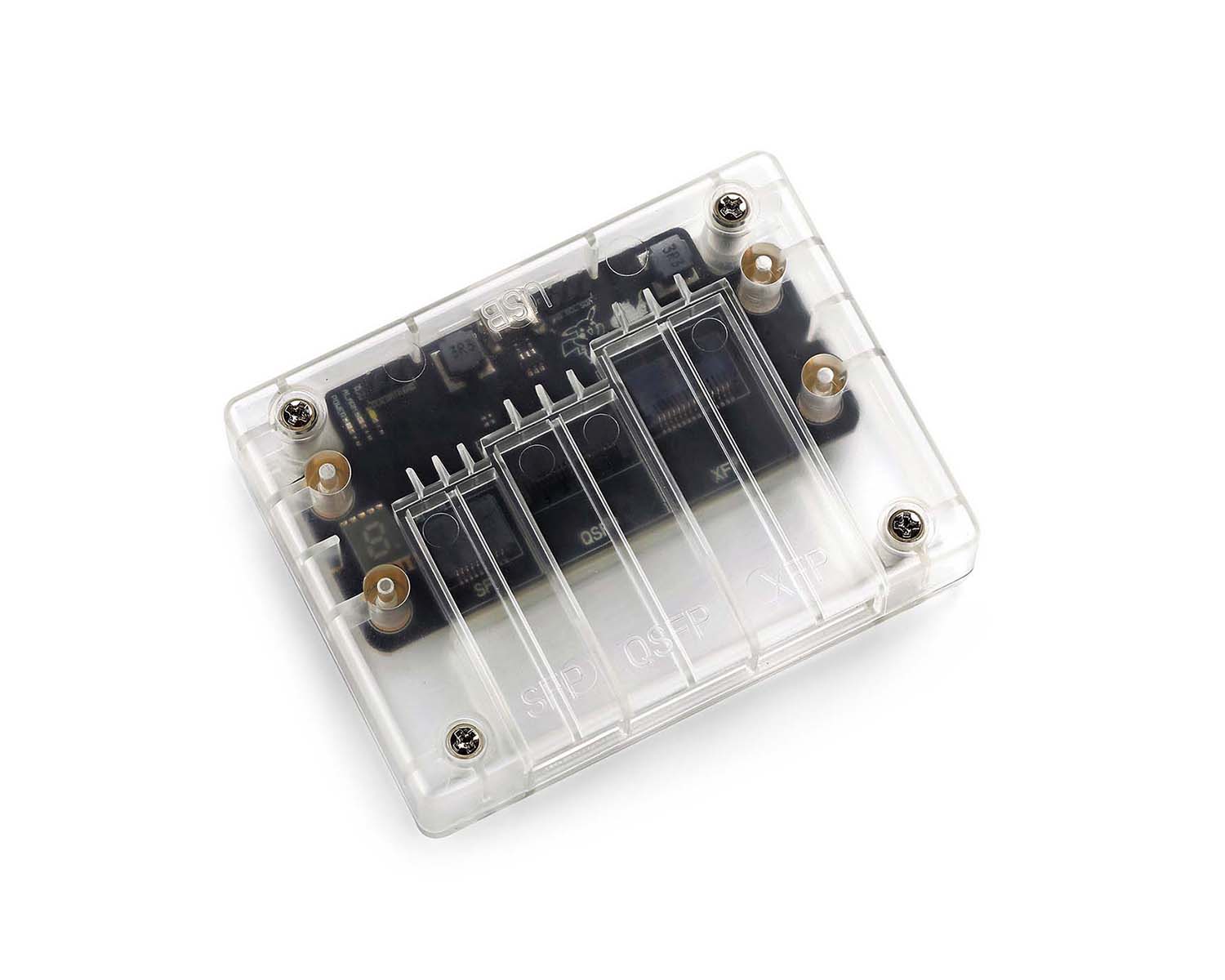 CodingBox
 QSFP to SFP Adapter
Structure Of Athermal Arrayed Waveguide Grating (AAWG) Module
Time: 2024-01-05
An Athermal Arrayed Waveguide Grating (AAWG) module is a dense wavelength division multiplexer (DWDM) based on PLC (Planar Lightwave Circuit) technology. Compared with DWDM devices made with TFF (Thin Film Filter) technology, it can support more channels.
The AAWG module uses mechanical compensation to reduce the impact of wavelength drift caused by temperature changes on the chip. It requires no external power supply and features high stability and reliability. Structurally, the main body of an AAWG module consists of six parts: single-channel input Fiber Array (FA), chip, multi-channel output Fiber Array (FA), compensation base, compensation rod with locking knob, and package housing, as shown in Figure 1.
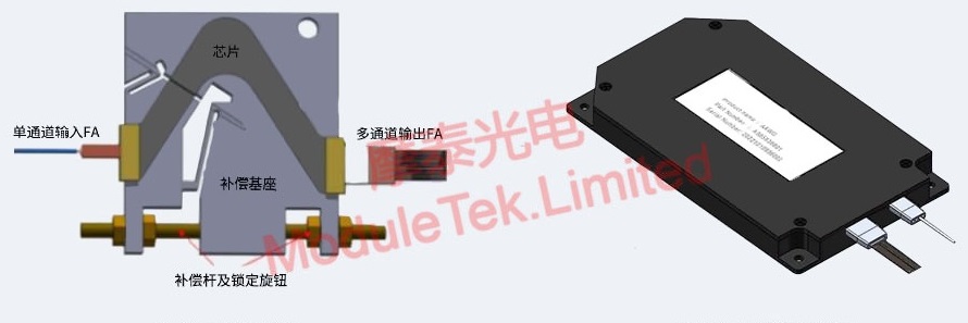
Figure 1 Main Structure and Package Structure of AAWG Module
Component Details
The chip is the core for implementing the arrayed waveguide grating function. It mainly includes the following five parts, as shown in Figure 2.
Figure 2 AAWG Chip Structure
① Input waveguides: Receive external wavelength signals.
② Input star coupler (also known as slab waveguide): Couples wavelength signals into the grating waveguides.
③ Grating waveguides: Transmit wavelength signals. The lengths of the waveguides increase sequentially by ΔL (length increment), generating a fixed optical path difference for the passing optical signals and functioning similarly to a grating.
④ Output star coupler (also known as slab waveguide): Focuses the diffracted wavelength signals into the output waveguides based on the interference principle, similar to Young’s double-hole interference.
⑤ Output waveguides: Distribute signals of different wavelengths to the receiving end.
Moduletek provides 40CH 100GHz C21–C60 DWDM MUX/DEMUX products based on athermal arrayed waveguide grating (AAWG) technology. Welcome to inquire and place orders.
For further inquiries about the above content, please contact us at: sales@moduletek.com