
 40G/100G Optical Transceivers
 25G Optical Transceivers
 10G Optical Transceivers
 155M/2.5G Optical Transceivers
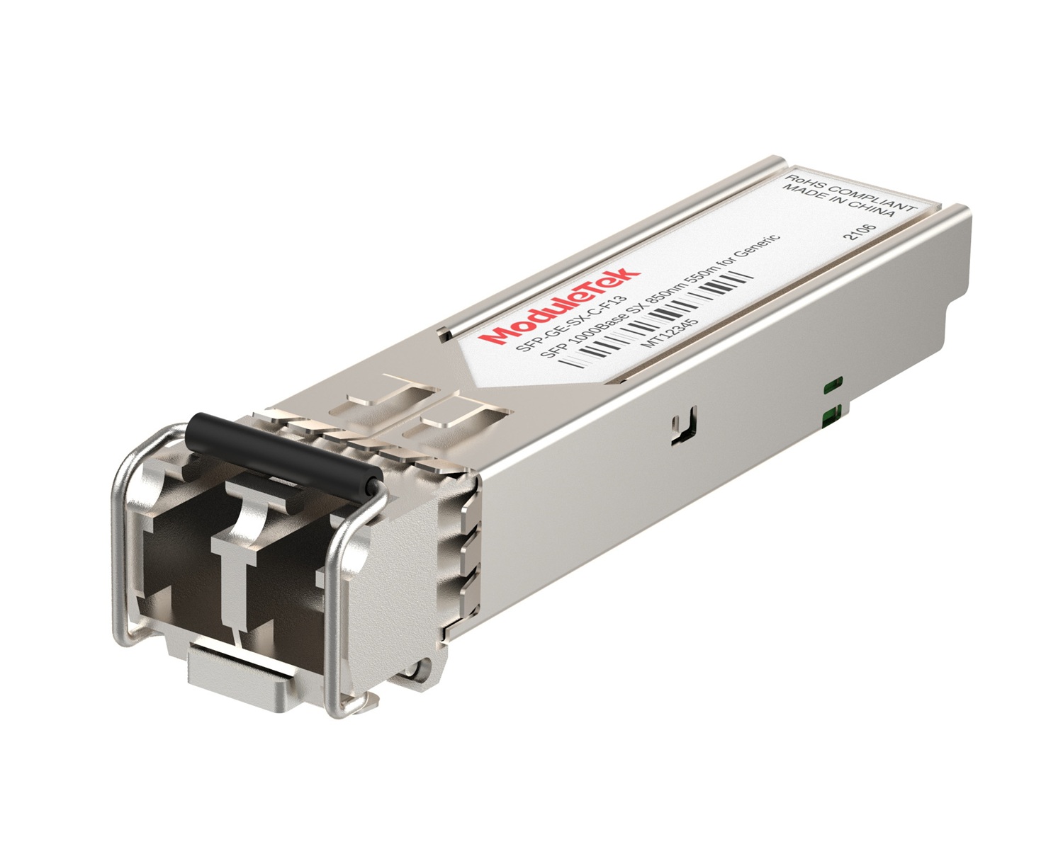 1G Optical Transceivers
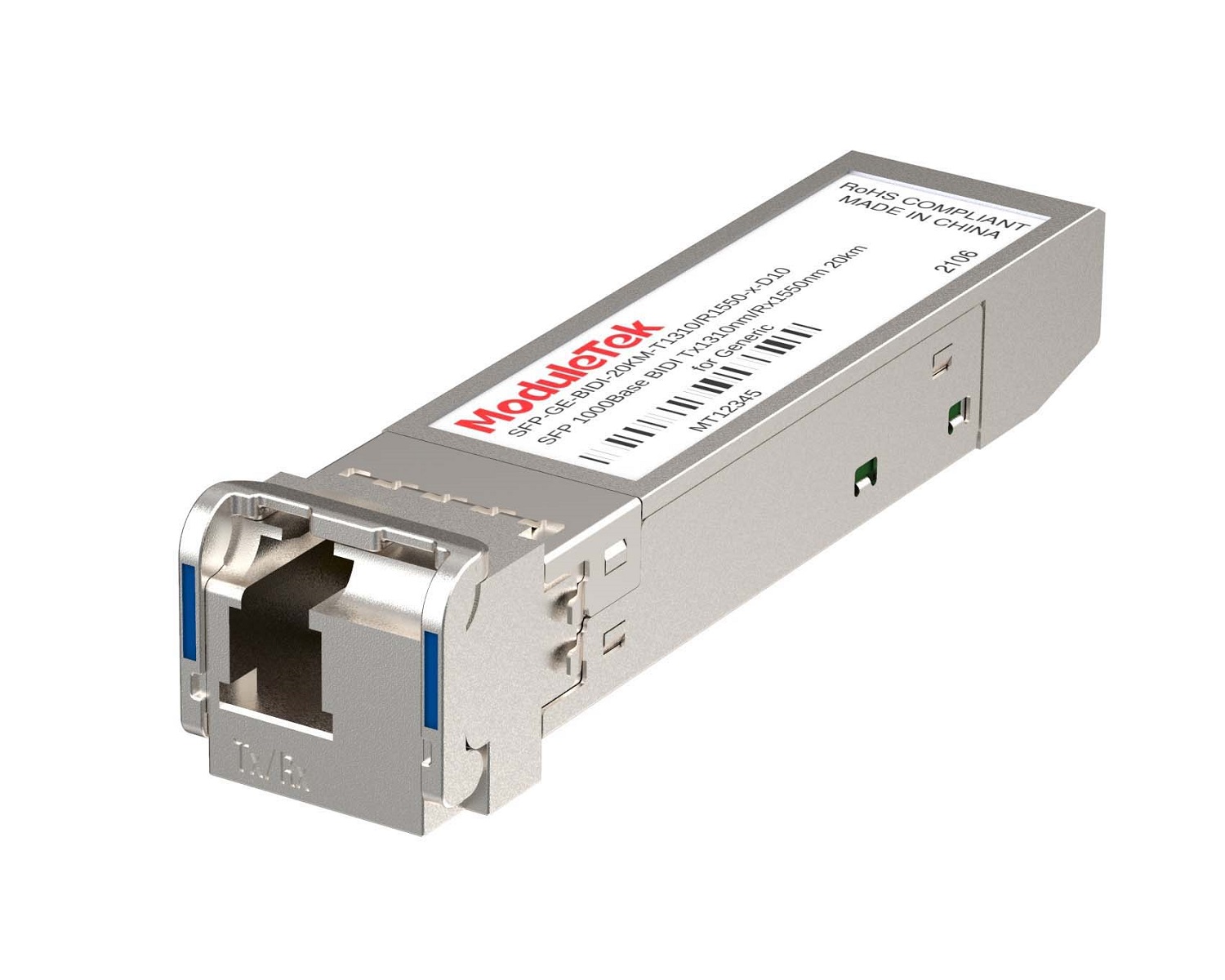 1G BIDI Optical Transceivers
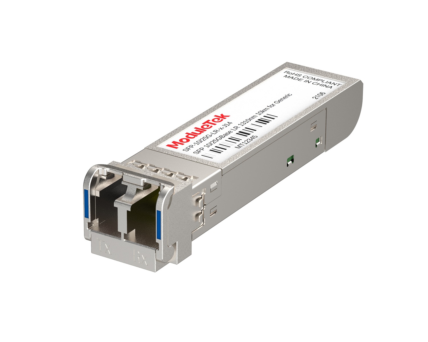 Dual-Rate Optical Transceivers
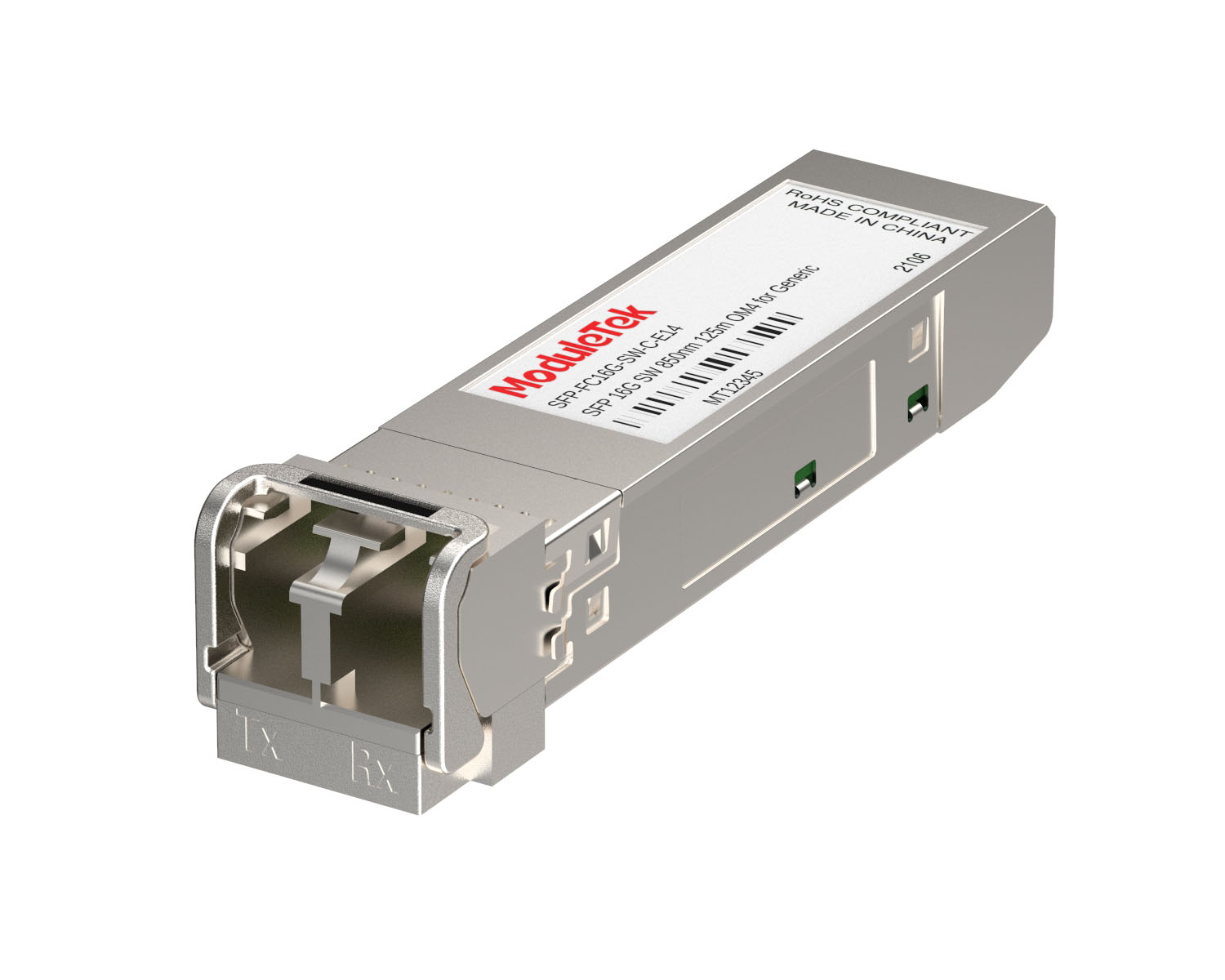 FC 16G/32G Optical Transceivers
 CWDM Optical Transceivers
 DWDM Optical Transceivers
 SGMII Port Optical Transceivers
 XFP Optical Transceivers
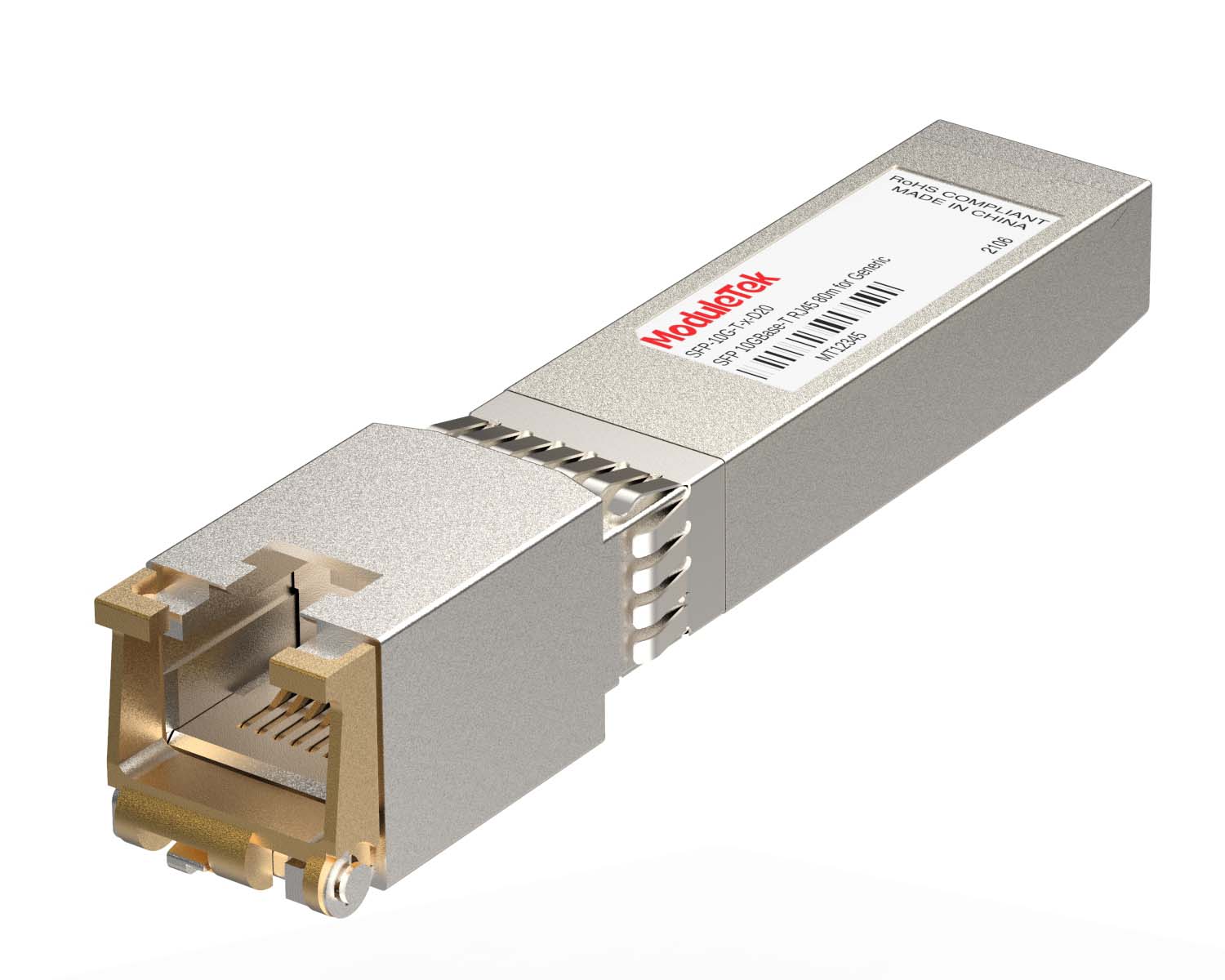 100M/1G/10G Coppers
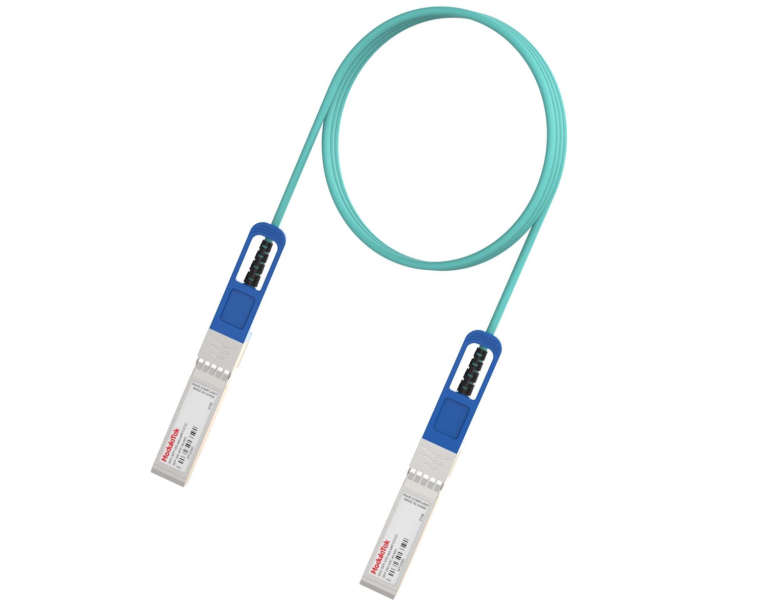 Full-Rate AOC & Breakout Series
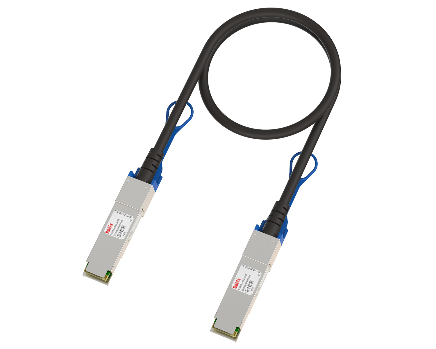 10G/40G Active DAC Series
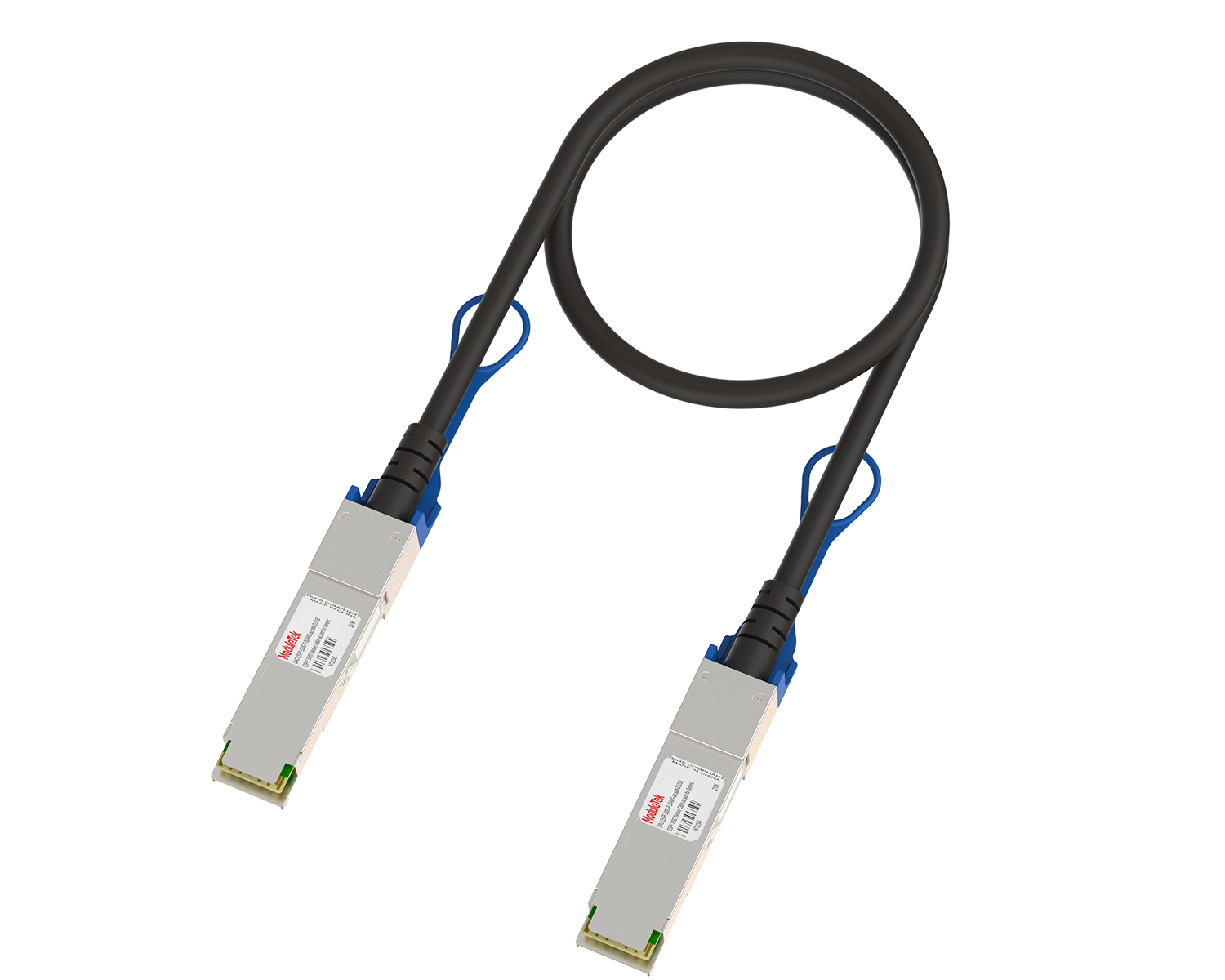 Full-Rate Passive DAC Series
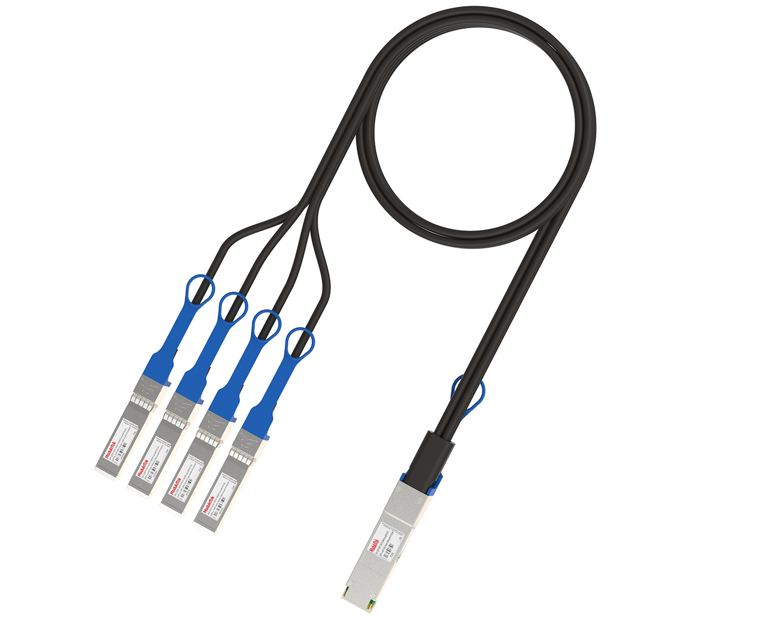 40G/100G Passive Breakout DAC Series
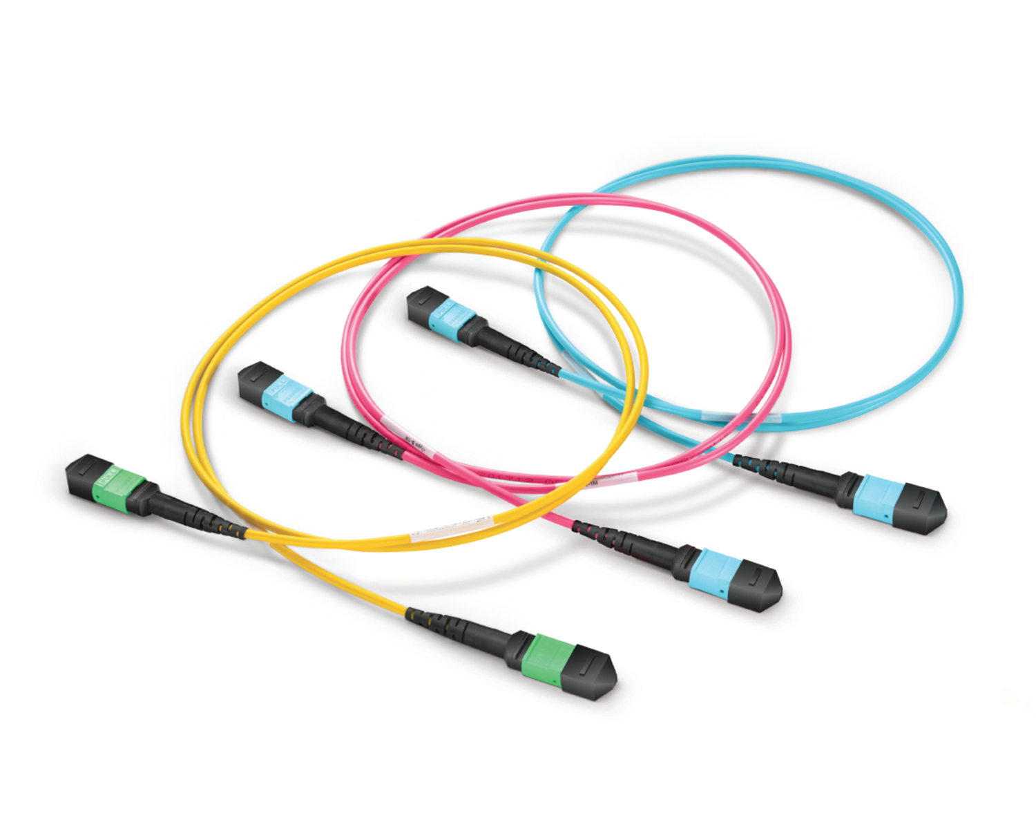 Regular/MTP-MPO Fiber Patch Cords
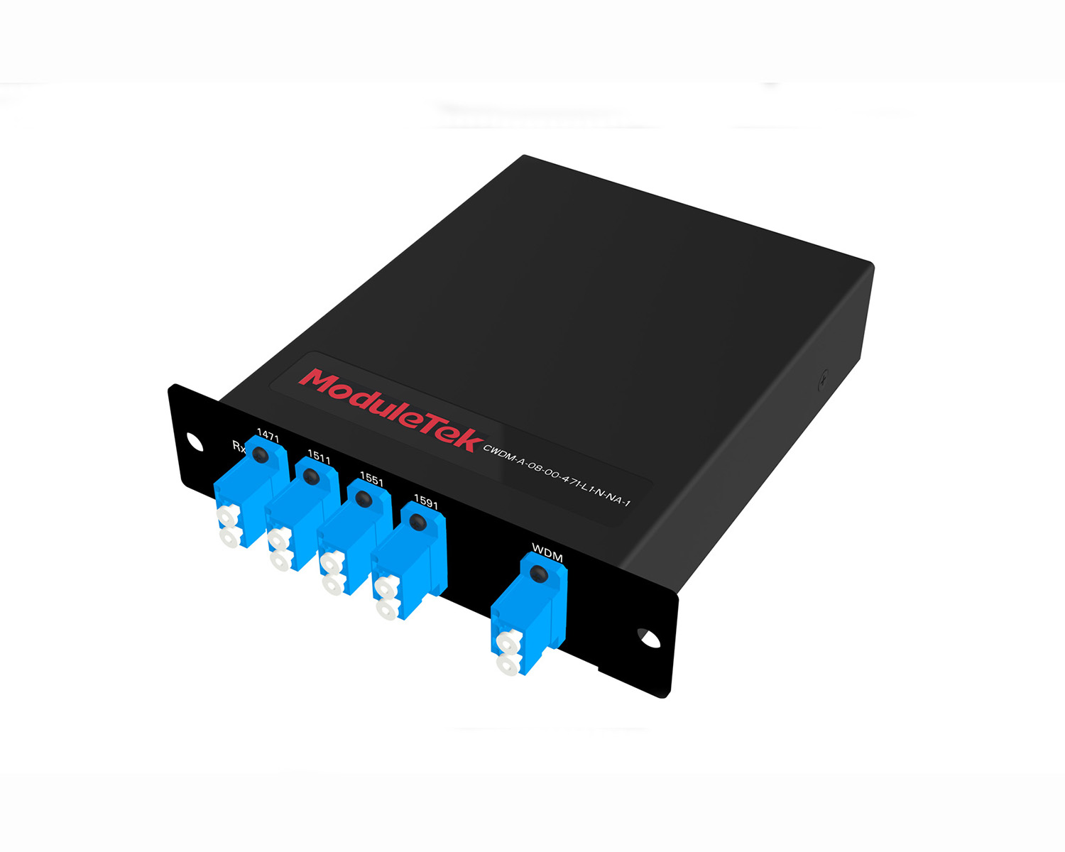 MT2011
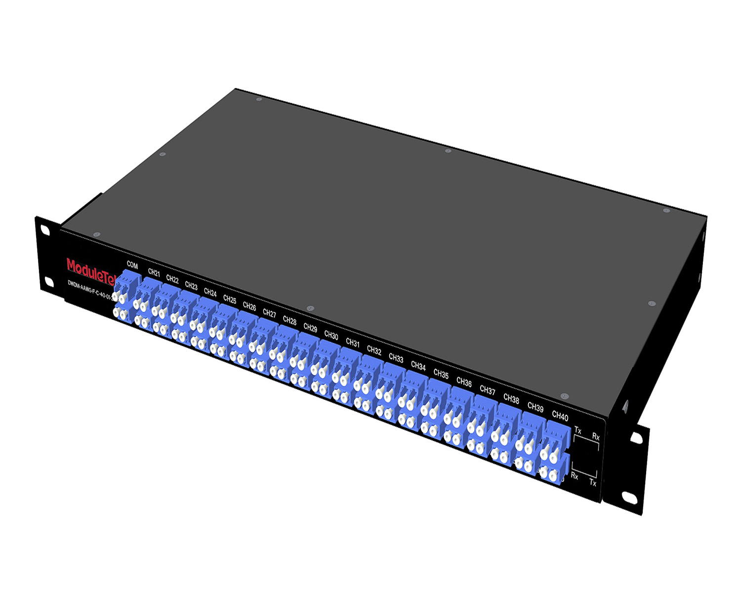 MT2010
 CodingBox
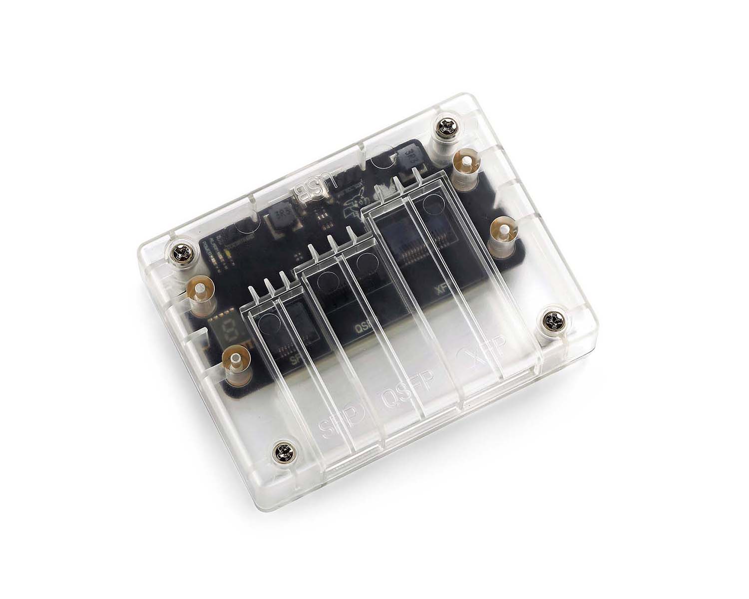
 QSFP to SFP Adapter
Optical Module Common Failure Of Optical Power Abnormality
Time: 2024-08-26
Digital Diagnostic Monitoring (DDM) Function Of Optical Modules enables real-time monitoring of module operation and fault location. Among them, transmit and receive optical power are core parameters for judging optical transceiver performance. This article sorts out common causes and corresponding solutions for abnormal transmit and receive optical power, helping users quickly locate and resolve network transmission faults.
1. Abnormal Transmit Optical Power
When optical transceivers at both ends of the link work normally, the transmit optical power must be within the product’s nominal threshold range (available via the product data sheet or by reading the module’s DOM data on the switch). Exceeding this range will cause abnormal module operation and affect network transmission. Specific troubleshooting methods are as follows:
1.1 Low Transmit Optical Power
• Impact: Causes low receive optical power at the opposite end, leading to packet loss or port failure to LINK UP;
• Causes: Fault in the transceiver’s own transmission function; for measured optical power (not DOM data), additionally check for contamination on the transmitting end face or damaged/faulty optical fiber;
• Solution: First clean the transmitting end face and optical fiber end face, then check fiber integrity; if the problem persists, replace the optical transceiver.
1.2 High Transmit Optical Power
• Impact: Causes high receive optical power at the opposite end, which may burn the opposite-end equipment after long-term operation;
• Causes: Fault in the local transceiver, resulting in abnormally high transmit power;
• Solution: Immediately replace the local transceiver to avoid damaging the opposite-end equipment.
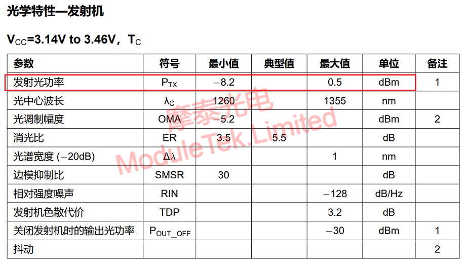
Figure 1 Moduletek 10G LR Transmit Optical Power Parameter Display
2. Abnormal Receive Optical Power
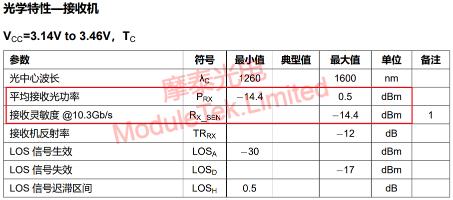
The receive optical power must match the transmit optical power and stay within the product’s nominal threshold range (same query method as transmit optical power). Exceeding this range will cause abnormal module operation. Specific troubleshooting methods are as follows:
2.1 Low Receive Optical Power
• Impact: Weak signal received by the local module, leading to packet loss, port failure to LINK UP, and other issues;
• Causes: Actual transmission distance exceeds the module’s nominal range; loose optical fiber connection; contamination or damage to the transceiver’s receiving end or optical fiber end face;
• Solution:
1. Deploy and use the module according to its nominal transmission distance;
2. Re-plug the optical fiber to ensure a secure connection;
3. Clean the module’s receiving end and optical fiber end face;
4. Replace damaged optical fiber or transceiver.
2.2 High Receive Optical Power
• Impact: Continuously high receive power may burn the local transceiver;
• Causes: Long-distance transceiver used for short-distance transmission; abnormal transmit power of the opposite-end transceiver; fault in the local transceiver’s receiving end;
• Solution:
1. If a long-distance transceiver is used for short-distance transmission, add an optical attenuator in the optical link to reduce receive power;
2. Troubleshoot and replace the faulty transceiver (opposite end or local end).
Figure 2 Moduletek 10G LR Receive Optical Power Parameter Display
Moduletek serves you wholeheartedly.
For further inquiries about the above content, please contact us at: sales@moduletek.com