 40G/100G Optical Transceivers
 25G Optical Transceivers
 10G Optical Transceivers
 155M/2.5G Optical Transceivers
 1G Optical Transceivers
 1G BIDI Optical Transceivers
 Dual-Rate Optical Transceivers
 FC 16G/32G Optical Transceivers
 CWDM Optical Transceivers
 DWDM Optical Transceivers
 SGMII Port Optical Transceivers
 XFP Optical Transceivers
 100M/1G/10G Coppers
 Full-Rate AOC & Breakout Series
 10G/40G Active DAC Series
 Full-Rate Passive DAC Series
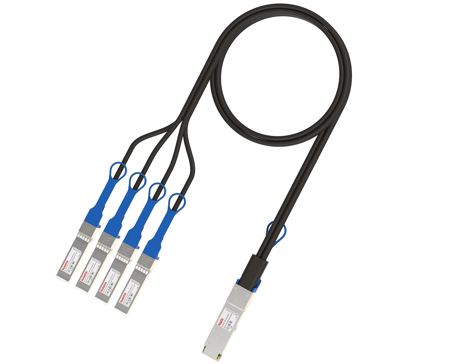 40G/100G Passive Breakout DAC Series
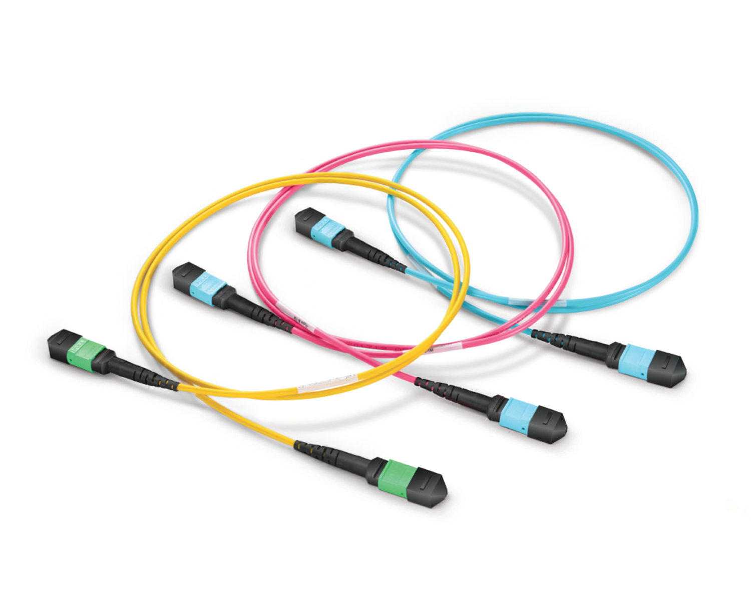 Regular/MTP-MPO Fiber Patch Cords
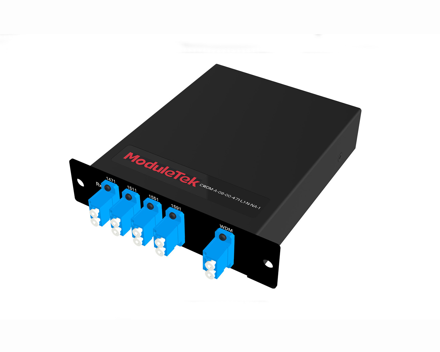 MT2011
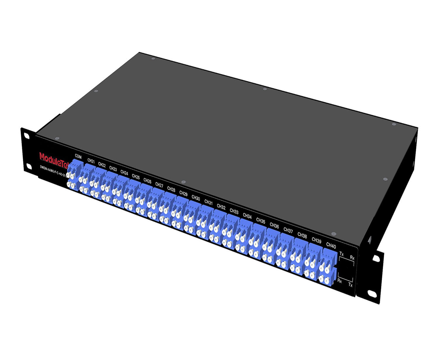 MT2010
 CodingBox
 QSFP to SFP Adapter
 首页 > Home > Application Notes > Introduction To Key Geometric Parameters Of Fiber Optic Patch Cord ConnecTors
Introduction To Key Geometric Parameters Of Fiber Optic Patch Cord ConnecTors
Time: 2019-04-25
⦁ Preface
Fiber optic patch cords are critical connectors in optical communications. To enhance the stability, reliability, and communication quality of high-speed networks, strict requirements are imposed on the parameters of fiber optic connectors.
Combined with international standard requirements, this article briefly introduces the parameters of LC connectors.
⦁ Parameter Requirements for Fiber Optic Connectors
1. Dimensional Specifications
Figure 1 below is a schematic diagram showing the appearance and dimensions of a ceramic ferrule for LC fiber optic patch cords:
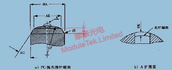
Figure 1 Ferrule Appearance and Dimension Diagram
International standards define several key dimensional specifications:
a. Outer Diameter of Ceramic Ferrule (ØA): Three grades are specified in international standards:
Table 1 Grading of Ceramic Ferrule Outer Diameter
|
Grade
|
Minimum Ø A(mm)
|
Maximum Ø A(mm)
|
Remarks
|
|
1
|
1.2485
|
1.2495
|
\
|
|
2
|
1.2483
|
1.2495
|
\
|
|
3
|
1.2487
|
1.2495
|
\
|
b. Step Outer Diameter (AE): International standard range: 0.60–0.85 mm;
c. Chamfer Angle (AG): International standard range: 32.5–37.5°;
2. 3D Interferometric Parameters
The 3D interferometric parameters of ceramic ferrules include curvature radius, fiber height and apex offset:
a. Curvature Radius: Refers to the radius of the curved surface at the top of the ferrule, corresponding to position AF in section a) PC Polished Ferrule Endface on the left of Figure 1. International standard requirement: 7–25 mm;
b. Fiber Height: Refers to the distance from the fiber endface to the ferrule endface, corresponding to position BK in section b) Enlarged View A on the right of Figure 1. International standard range: -50–+50 nm.
Here, the "+" sign indicates that the fiber endface is higher than the ferrule endface, while the "-" sign indicates that the fiber endface is lower than the ferrule endface (i.e., the fiber endface is recessed relative to the ferrule endface), as shown in the detailed schematic diagram below:
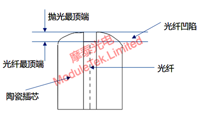
Figure 2 Fiber Height Schematic Diagram
c. Apex Offset: Refers to the offset distance from the topmost point of the ferrule to the fiber core, as shown in the detailed schematic diagram below:
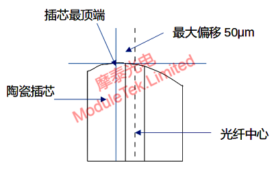
Figure 3 Apex Offset Schematic Diagram
International standard range: 0–50 μm;
Moduletek offers a wide range of fiber optic patch cord products. Welcome to contact us for inquiries and purchases.
For further inquiries about the above content, please contact us at: sales@moduletek.com


