 40G/100G Optical Transceivers
 25G Optical Transceivers
 10G Optical Transceivers
 155M/2.5G Optical Transceivers
 1G Optical Transceivers
 1G BIDI Optical Transceivers
 Dual-Rate Optical Transceivers
 FC 16G/32G Optical Transceivers
 CWDM Optical Transceivers
 DWDM Optical Transceivers
 SGMII Port Optical Transceivers
 XFP Optical Transceivers
 100M/1G/10G Coppers
 Full-Rate AOC & Breakout Series
 10G/40G Active DAC Series
 Full-Rate Passive DAC Series
 40G/100G Passive Breakout DAC Series
 Regular/MTP-MPO Fiber Patch Cords
 MT2011
 MT2010
 CodingBox
 QSFP to SFP Adapter
Introduction To BOX-Packaged EML TOSA
Time: 2020-02-23
⦁ Overview
EML (Electro-absorption Modulated Lasers) TOSAs are adopted for the transmitting ends of 40km and 80km 1550nm optical modules. Common EML TOSAs come in two packaging types: BOX package and coaxial package. However, considering heat dissipation and performance comprehensively, the BOX package is the more commonly used option. This article will introduce the structure and working principle of the BOX-packaged EML TOSA.
1. Outline Structure and Internal Functional Schematic of BOX TOSA
Outline Structure of BOX TOSA
As the name implies, the TO part of a BOX-packaged TOSA is box-shaped, featuring a relatively large internal space. Figure 1 below shows the outline dimension drawing of the BOX EML TOSA currently in mass production at our company:
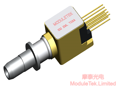
Figure 1 Outline Dimension Drawing of BOX EML TOSA
As illustrated in the figure above: the total length of the BOX EML TOSA is 17.6mm, and the length, width and height of the TO part are 7.5mm, 5.5mm and 5.5mm respectively. The large inner cavity of the TO allows the use of a large-packaged TEC (Thermoelectric Cooler). In addition, the outer wall of the TO is made of 0.8mm-thick alloy material, which boasts excellent heat conduction and dissipation properties.
2. Internal Functional Block Diagram of BOX EML TOSA
The BOX EML TOSA consists of five internal components: DFB laser, EAM, MPD, TEC and Rth, as shown in the figures below:
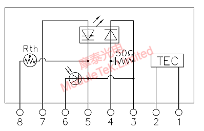
Figure 2 Internal Circuit Diagram of BOX EML TOSA
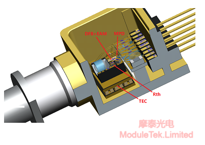
Figure 3 Internal Structural and Functional Schematic of BOX EML TOSA
Figure 2 shows the internal circuit diagram of a typical EML TOSA, and Figure 3 presents the internal structural and functional schematic of a typical BOX EML TOSA. The detailed working principles and control methods of each functional circuit are described as follows:
A. DFB Laser
The DFB (Distributed Feedback) laser is connected across Pin 7 and Pin 5 in Figure 2, with Pin 5 grounded. When the current input to Pin 7 exceeds the threshold current (ranging from 15 to 30mA), the DFB laser starts emitting light. During normal operation, the DFB laser requires a current supply of 50 to 100mA.
B. EAM (Electro-absorption Modulator)
The EAM is connected across Pin 4 and Pin 3 in Figure 2, with Pin 3 grounded. A negative voltage (ranging from -3V to 0V during normal operation) needs to be applied to Pin 4 to reverse-bias the EAM. The lower the voltage at Pin 4, the more light the EAM absorbs, and the less light passes through it; conversely, the higher the voltage at Pin 4, the more light passes through the EAM. A typical EAM absorption curve is shown in the figure below:
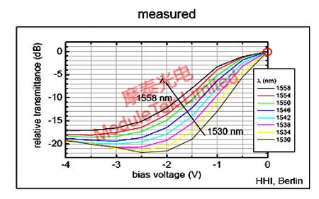
Figure 4 EAM Absorption Characteristic Curve
C. MPD (Monitor Photodetector)
The MPD is connected across Pin 6 and Pin 3 in Figure 2. It is used to monitor the output optical power of the DFB laser. Generally, a certain proportion of the light emitted by the DFB laser in the reverse direction (commonly referred to as "backlight") irradiates the MPD, generating an MPD current. Typically, the magnitude of the MPD current is proportional to the forward output optical power of the DFB laser. Therefore, the output optical power of the DFB laser can be tracked by monitoring the MPD current.
D. TEC (Thermoelectric Cooler)
The TEC is connected across Pin 1 and Pin 2 in Figure 2. It is fabricated based on the Peltier Effect, which refers to the phenomenon where one end of a thermocouple composed of two semiconductor materials absorbs heat while the other end releases heat when direct current flows through it. The TEC is composed of several P-type and N-type thermocouple pairs connected via electrodes and sandwiched between two ceramic plates. When current flows through the TEC, the heat generated by the current is transferred from one side of the TEC to the other, creating a "hot side" and a "cold side". The TEC controller dynamically adjusts the magnitude and direction of the current flowing through the TEC according to the temperature of the TEC surface, maintaining the TEC surface temperature in a dynamically stable state.
E. Rth (Thermistor)
The Rth is connected across Pin 8 and Pin 5 in Figure 2. Its resistance value has a corresponding relationship with temperature: the higher the temperature, the smaller the resistance; the lower the temperature, the larger the resistance. At 25℃, the resistance value of Rth is 10 kΩ. The Rth is generally integrated with the TEC controller to form a dynamic feedback control system. It realizes the temperature stability of the TEC surface (where the DFB and EAM are located) by dynamically adjusting the current through the TEC based on the PID control algorithm.
Moduletek supplies the products mentioned in this application guide. Welcome to place your orders!
For further inquiries about the above content, please contact us at: sales@moduletek.com


