 40G/100G Optical Transceivers
 25G Optical Transceivers
 10G Optical Transceivers
 155M/2.5G Optical Transceivers
 1G Optical Transceivers
 1G BIDI Optical Transceivers
 Dual-Rate Optical Transceivers
 FC 16G/32G Optical Transceivers
 CWDM Optical Transceivers
 DWDM Optical Transceivers
 SGMII Port Optical Transceivers
 XFP Optical Transceivers
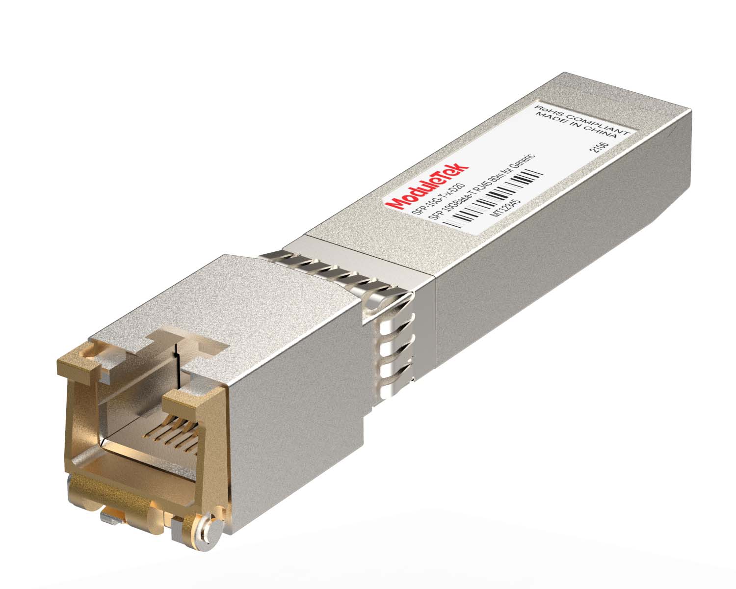 100M/1G/10G Coppers
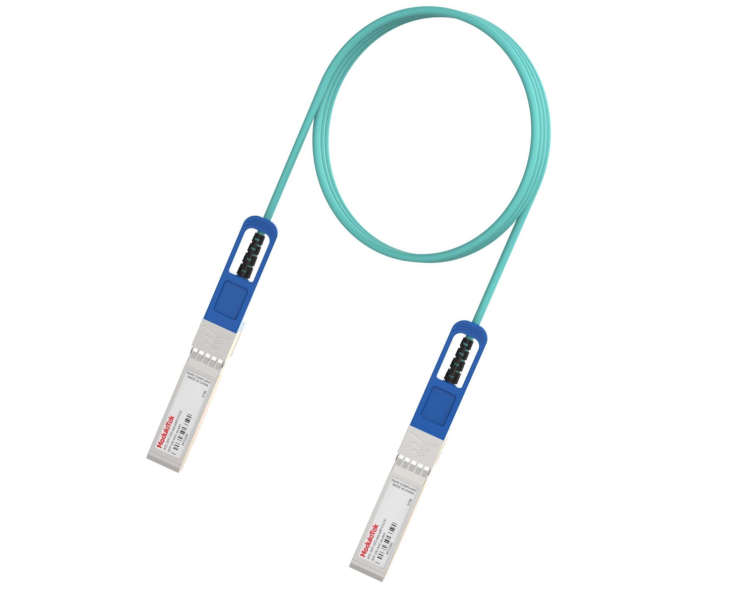 Full-Rate AOC & Breakout Series
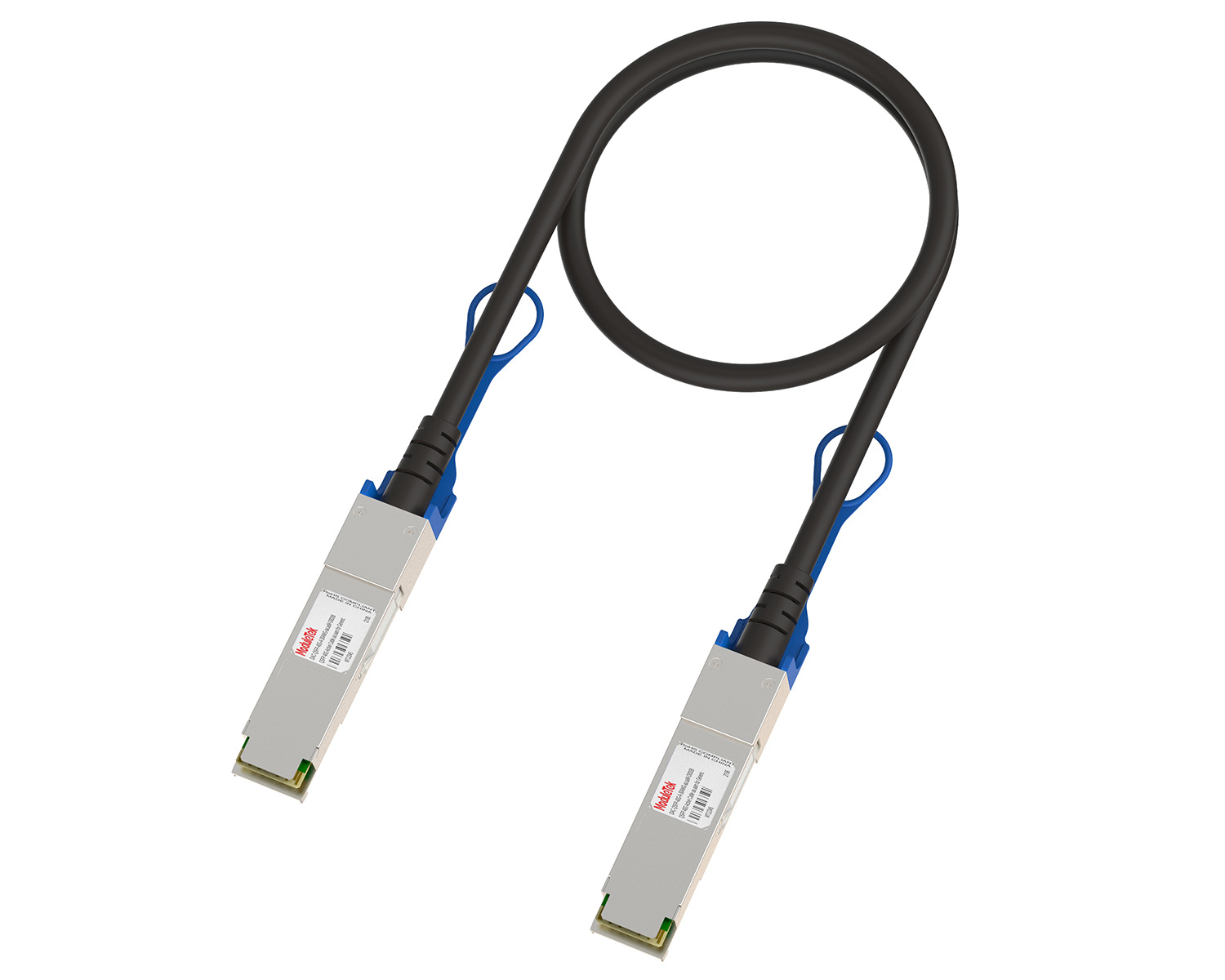 10G/40G Active DAC Series
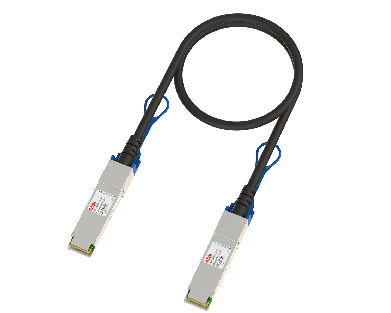 Full-Rate Passive DAC Series
 40G/100G Passive Breakout DAC Series
 Regular/MTP-MPO Fiber Patch Cords
 MT2011
 MT2010
 CodingBox
 QSFP to SFP Adapter
 首页 > Home > Application Notes > Technical Characteristics Of 10G Optical Modules With 1310nm And 1550nm Wavelengths In Applications
Technical Characteristics Of 10G Optical Modules With 1310nm And 1550nm Wavelengths In Applications
Time: 2020-02-23
1. Optical Communication Wavelengths
There are three wavelength windows for 10G optical module communication applications, namely the 850nm window, 1310nm window, and 1550nm window. The 850nm wavelength is applied to multimode fibers, while the 1310nm and 1550nm wavelengths are used for single-mode fibers. In practical single-mode fiber applications, users often have questions about the advantages and disadvantages of the 1310nm and 1550nm wavelengths, as well as how to select the appropriate wavelength. This article aims to explore this issue.
2. 1310nm vs. 1550nm
2.1 Attenuation Characteristics
Optical signals of different wavelengths exhibit different attenuation coefficients when transmitted over a unit length of optical fiber. Taking G652 fiber as an example, Figure 1 below shows the transmission attenuation of optical signals at different wavelengths:
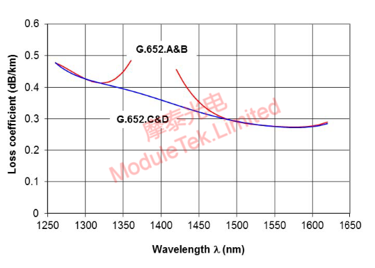
Figure 1 Schematic Diagram of Transmission Attenuation Coefficients at Different Wavelengths
As shown in the figure above:
On G652 C&D fiber, the attenuation coefficient α of the 1270nm wavelength is 0.46dB/km, that of the 1310nm wavelength is 0.42dB/km, and that of the 1550nm wavelength is 0.28dB/km.
The transmission attenuation of optical signals over optical fiber is calculated by the formula: Loss = α * L (where Loss is in dB, α is in dB/km, and L is in km).
Table 1 Calculated Attenuation of Different Wavelengths Over Different Transmission Distances
|
Distance
|
500m(dB)
|
2km(dB)
|
10km(dB)
|
40km(dB)
|
80km(dB)
|
|
1310nm
|
0.21
|
0.84
|
4.2
|
16.8
|
33.6
|
|
1550nm
|
0.14
|
0.56
|
2.8
|
11.2
|
22.4
|
2.2 Dispersion Characteristics
Dispersion, also known as pulse broadening, is a physical characteristic of optical signal transmission in optical fibers. Its specific manifestations are as follows: input signal pulses are distinct and non-overlapping; output pulses show pulse broadening, leading to pulse overlap and indistinguishability between pulses; the optical fiber bandwidth decreases as dispersion increases. See the figure below for details:
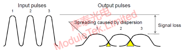
Figure 2 Schematic Diagram of Dispersion - Transmission Pulse Broadening
Optical signals of different wavelengths have different dispersion levels when transmitted in optical fibers, as shown in Figure 3 below:
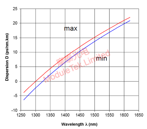
Figure 3 Schematic Diagram of Transmission Dispersion Coefficients at Different Wavelengths
The dispersion coefficient is denoted as D (unit: ps/nm·km). On G652 C&D fiber, the maximum dispersion coefficient D of the 1310nm wavelength is 0.91ps/nm·km, that of the 1330nm wavelength is 2.7ps/nm·km, and that of the 1550nm wavelength is 18.2ps/nm·km. The chromatic dispersion - induced pulse broadening of optical signals transmitted over optical fiber is calculated by the formula: CD = D * L (where CD is in ps, D is in ps/nm·km, and L is in km).
3. Parameter Comparison of 10G Optical Modules with 1310nm and 1550nm Wavelengths
Technically, 10G optical modules with 1310nm wavelength utilize uncooled DFB lasers, resulting in a lower cost. The output optical power of such modules can reach approximately 1 - 2mW, the laser operating current is usually around 30 - 50mA, and the module power consumption at room temperature is about 0.8W. Due to the relatively high fiber attenuation, the transmission distance is typically within 40km. 1310nm wavelength optical modules are widely used in application scenarios with transmission distances ranging from several hundred meters to tens of kilometers.
In contrast, 10G optical modules with 1550nm wavelength usually require EML lasers with a cooler. Their output optical power can also reach around 1 - 2mW, the laser operating current is generally 70 - 100mA, and the module power consumption at room temperature is less than 1.2W. At a high temperature of 75°C, the TEC current increases, causing the module power consumption to rise to 1.5W. These modules are usually applied in optical fiber transmission environments with distances of 40 - 80km. Due to the limited application scenarios of 40 - 80km, as well as the more complex components and manufacturing processes, this type of module is relatively expensive.
The specific parameter comparison between the two types of 10G optical modules with different wavelengths is shown in the table below:
Table 2 Comparison Between 1310nm and 1550nm Optical Modules
|
Wavelength
|
Output Optical Power
|
Extinction Ratio
|
Bias Current
|
Power Consumption
|
Transmission Distance
|
|
1310nm(DFB)
|
0~5dBm
|
<4dB
|
30~50mA
|
<1.2W
|
小于40km
|
|
1550nm(EML)
|
-4~4dBm
|
8~12dBm
|
60~100mA
|
<1.5W
|
40~80km
|
Therefore, in practical project applications, we should comprehensively choose the module type and wavelength based on the link transmission distance, fiber attenuation coefficient, dispersion coefficient, power consumption control requirements, and cost budget.
can provide optical module products with the above two wavelengths. Welcome to place your orders!
For further inquiries about the above content, please contact us at: sales@moduletek.com


