 40G/100G Optical Transceivers
 25G Optical Transceivers
 10G Optical Transceivers
 155M/2.5G Optical Transceivers
 1G Optical Transceivers
 1G BIDI Optical Transceivers
 Dual-Rate Optical Transceivers
 FC 16G/32G Optical Transceivers
 CWDM Optical Transceivers
 DWDM Optical Transceivers
 SGMII Port Optical Transceivers
 XFP Optical Transceivers
 100M/1G/10G Coppers
 Full-Rate AOC & Breakout Series
 10G/40G Active DAC Series
 Full-Rate Passive DAC Series
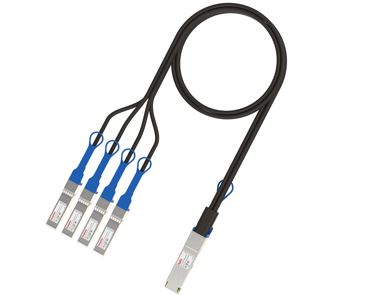 40G/100G Passive Breakout DAC Series
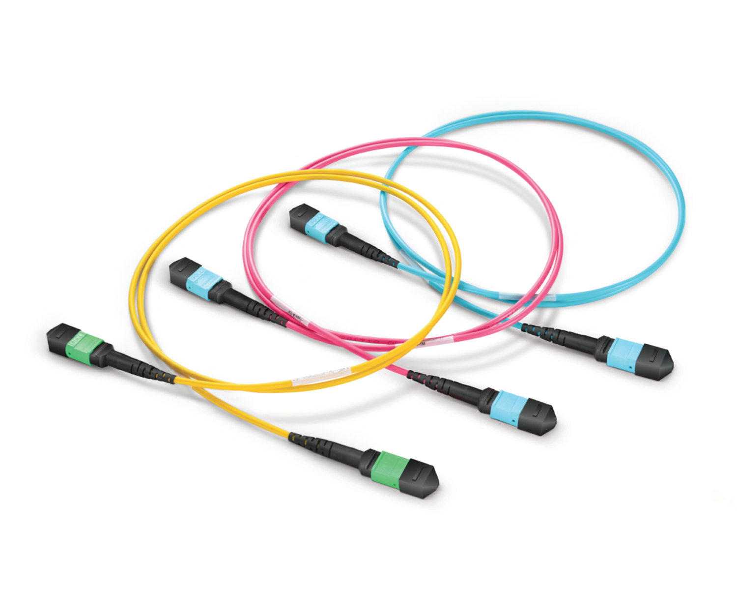 Regular/MTP-MPO Fiber Patch Cords
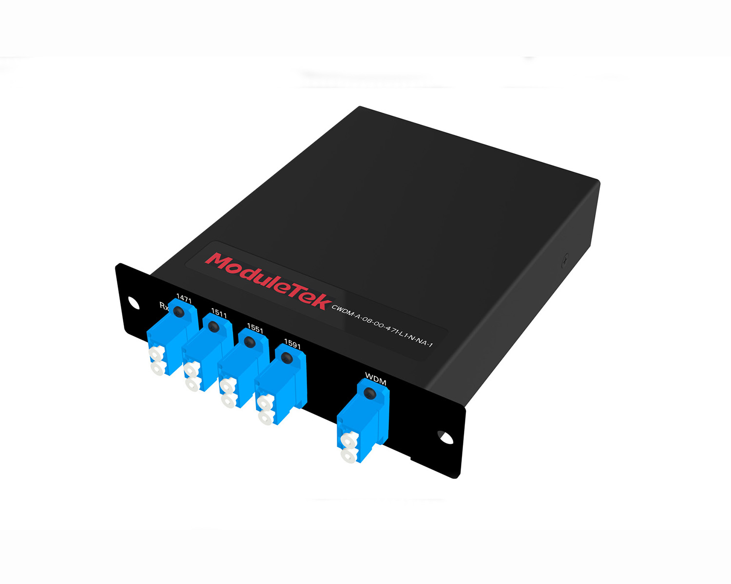 MT2011
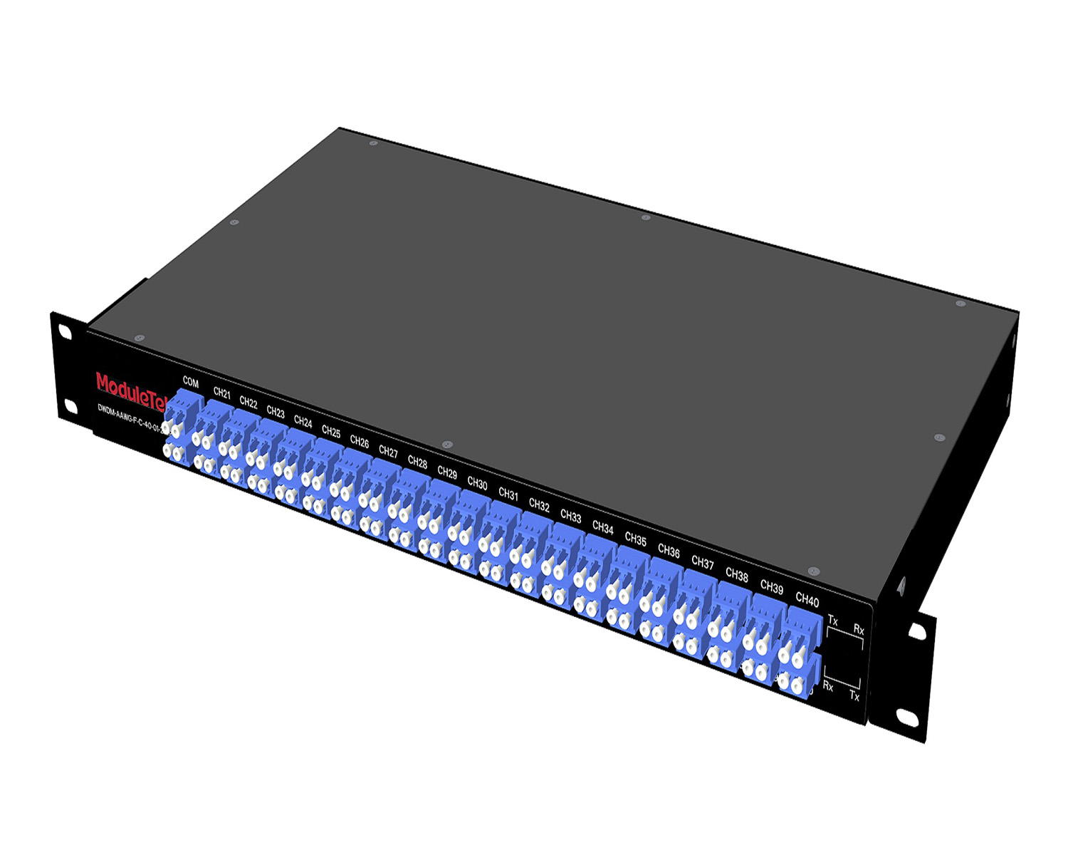 MT2010
 CodingBox
 QSFP to SFP Adapter
 首页 > Home > Application Notes > New Data Center Network Architecture Transforms To "Leaf-Spine Architecture"
New Data Center Network Architecture Transforms To "Leaf-Spine Architecture"
Time: 2022-05-24
In recent years, with the booming development of the Internet, especially mobile Internet, applications such as big data, mobile payment, cloud storage, video media, and Internet of Vehicles (IoV) have put forward higher requirements for data centers in terms of high-speed access, high-performance computing, massive data storage, and flexible service migration. In response, major Internet and IDC enterprises have successively built high-performance, highly reliable, and service-flexible large Layer 2 networks in their data centers.
The traditional three-tier architecture consists of a core layer, aggregation layer, and access layer, but it has a prominent technical contradiction between reliability and link utilization. To achieve multi-device and multi-path redundancy in this architecture, the STP protocol is enabled to avoid loops and broadcast storms, which leads to extremely low link utilization efficiency.
Another shortcoming of this architecture is that it was originally designed mainly for north-south traffic. Although it also supports east-west traffic, it has obvious drawbacks. As shown in Figure 1, east-west traffic needs to follow the path: access → aggregation → core → aggregation → access. This not only wastes core switch resources but also significantly increases latency due to multi-layer forwarding. Moreover, inconsistent hop counts of packet forwarding paths lead to uneven packet transmission, further affecting end-user access response time.
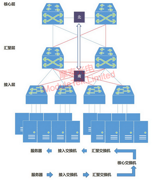
Figure 1 Traditional Three-Tier Architecture
Essentially, the traditional three-tier architecture only ensures transmission redundancy and is not fully adaptable to data center network requirements with changes in data flow directions. The emergence of the Leaf-Spine network architecture and related protocols effectively addresses the shortcomings of the traditional three-tier architecture, forming a large Layer 2 network that better meets the needs of data center cloud computing and virtualization technologies for network performance and flexible service migration.
The Leaf-Spine network architecture consists of a Leaf layer and a Spine layer. Leaf switches act as access switches to connect servers, storage devices, and other endpoints, while Spine switches act as the backbone layer responsible for routing and forwarding. In this architecture, each Leaf switch is fully interconnected with every Spine switch, forming a fully meshed topology, as shown in Figure 2:
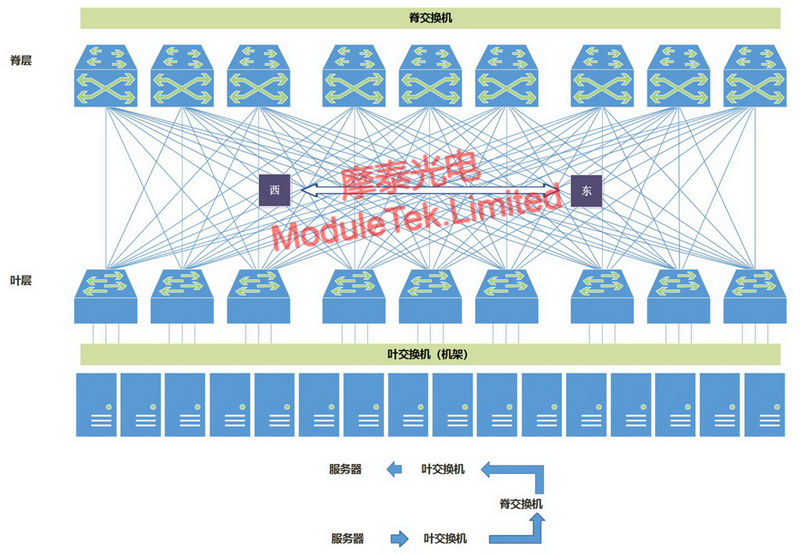
Figure 2 Leaf-Spine Network Architecture
Core Advantages of the Leaf-Spine Network Architecture
1. Low Latency: Traffic between servers on different Leaf switches only needs one hop of forwarding through a Spine switch to reach the target Leaf switch. This ensures equal-length paths for packets, predictable latency, and significantly reduced forwarding times, thereby lowering overall latency.
2. High Efficiency: It uses ECMP (Equal-Cost Multi-Path) for load balancing, dynamically selecting multiple paths for communication. Compared with the STP protocol used in traditional Layer 2 networks, it can better utilize multiple links for traffic transmission, greatly improving link utilization efficiency.
3. High Scalability: Different Leaf switches in the same domain provide access with consistent paths and latency, enabling flexible service migration across switches in the large Layer 2 network. When bandwidth is insufficient, horizontal bandwidth expansion can be achieved by adding Spine switches; when the number of servers increases, adding Leaf switches can expand the data center scale, which is more conducive to the application of cloud computing and virtualization technologies.
4. Lower Hardware Requirements: North-south traffic can be forwarded out from either Leaf or Spine nodes. East-west traffic is distributed across multiple links, which significantly reduces the demand for expensive high-bandwidth, high-performance switches.
5. Higher Reliability: Traditional networks rely on the STP protocol, which requires re-convergence when a device fails, affecting network performance or even causing outages. The Leaf-Spine architecture adopts the TRILL protocol (Transparent Interconnection of Lots of Links), which avoids re-convergence when a device fails. Traffic automatically switches to other normal paths, ensuring uninterrupted network connectivity. Only the bandwidth of the faulty path is lost, with negligible impact on overall performance.
Currently, data traffic between data centers has increased dramatically, and the Leaf-Spine architecture demonstrates excellent performance in inter-IDC data transmission. When deployed with a reasonable Leaf-to-Spine bandwidth ratio of no more than 3:1, the demand for optical modules in this architecture is at least 5 times that of the traditional architecture, significantly increasing the usage of optical modules and patch cords. As shown in Table 1 (data compiled from public sources):
Table 1 Comparison of Optical Module Demand Between Leaf-Spine and Traditional Architecture
|
Data Center
|
Architecture
|
Number of Optical Modules
|
||
|
10G
|
40G
|
100G
|
||
|
Small Data Center (960 servers)
|
Traditional Architecture
|
2000
|
16
|
4
|
|
Leaf-Spine Architecture
|
1920
|
160
|
16
|
|
|
Medium & Large Data Center (1000 racks)
|
Traditional Architecture
|
128000
|
160
|
8
|
|
Leaf-Spine Architecture
|
120000
|
4800
|
32
|
|
For further inquiries about the above content, please contact us at: sales@moduletek.com


