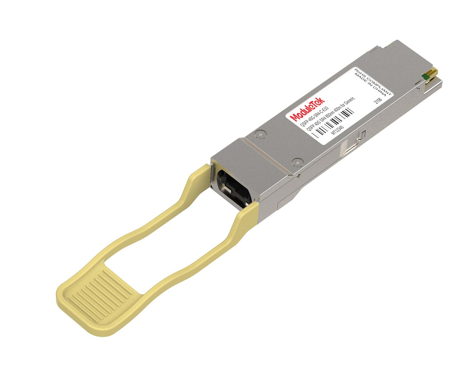
 40G/100G Optical Transceivers
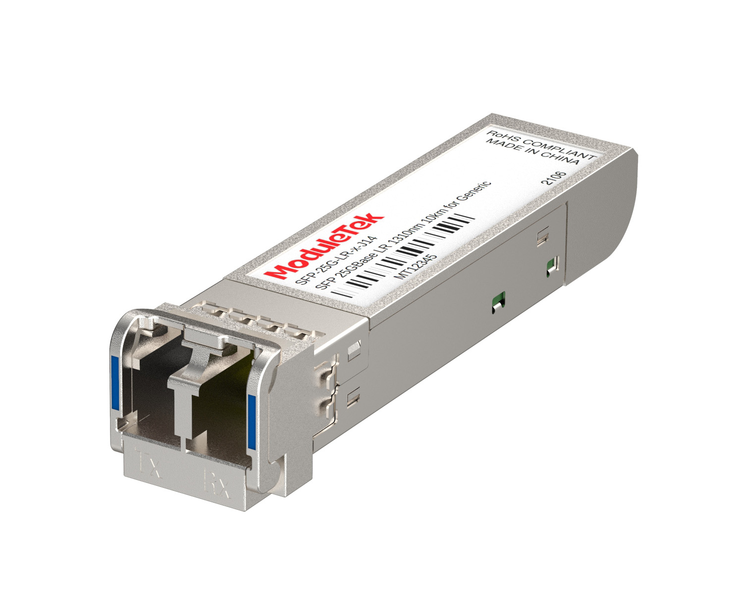 25G Optical Transceivers
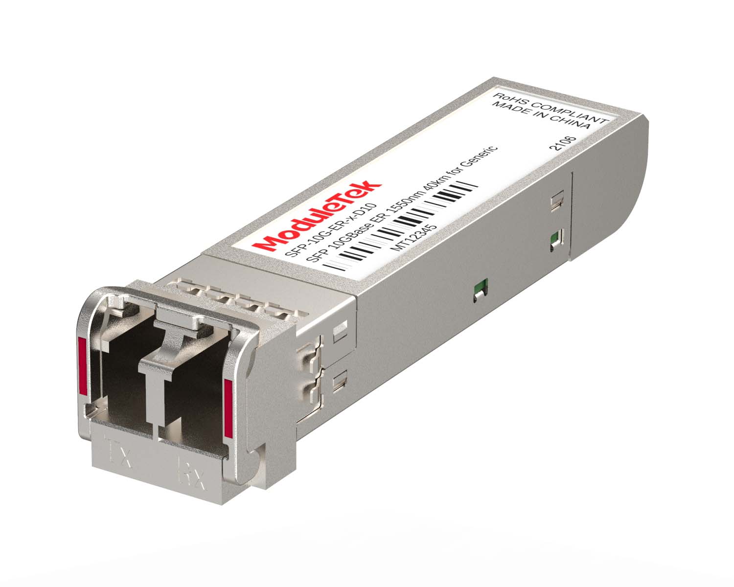 10G Optical Transceivers
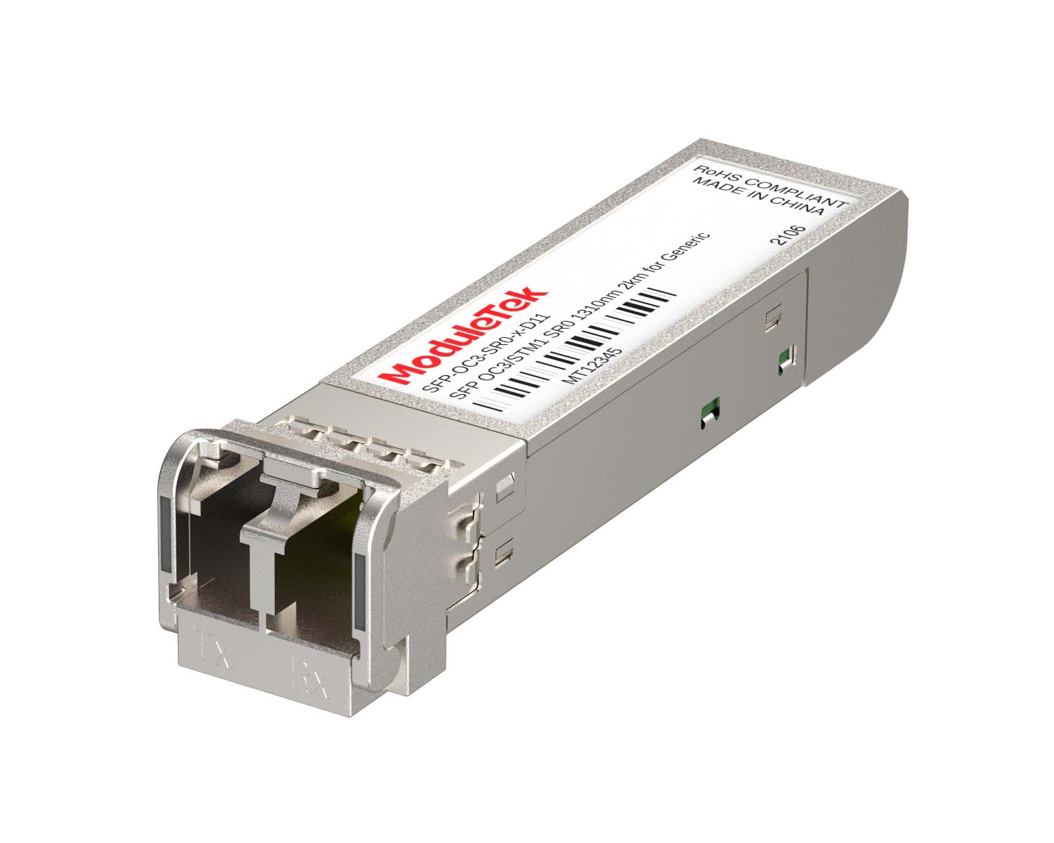 155M/2.5G Optical Transceivers
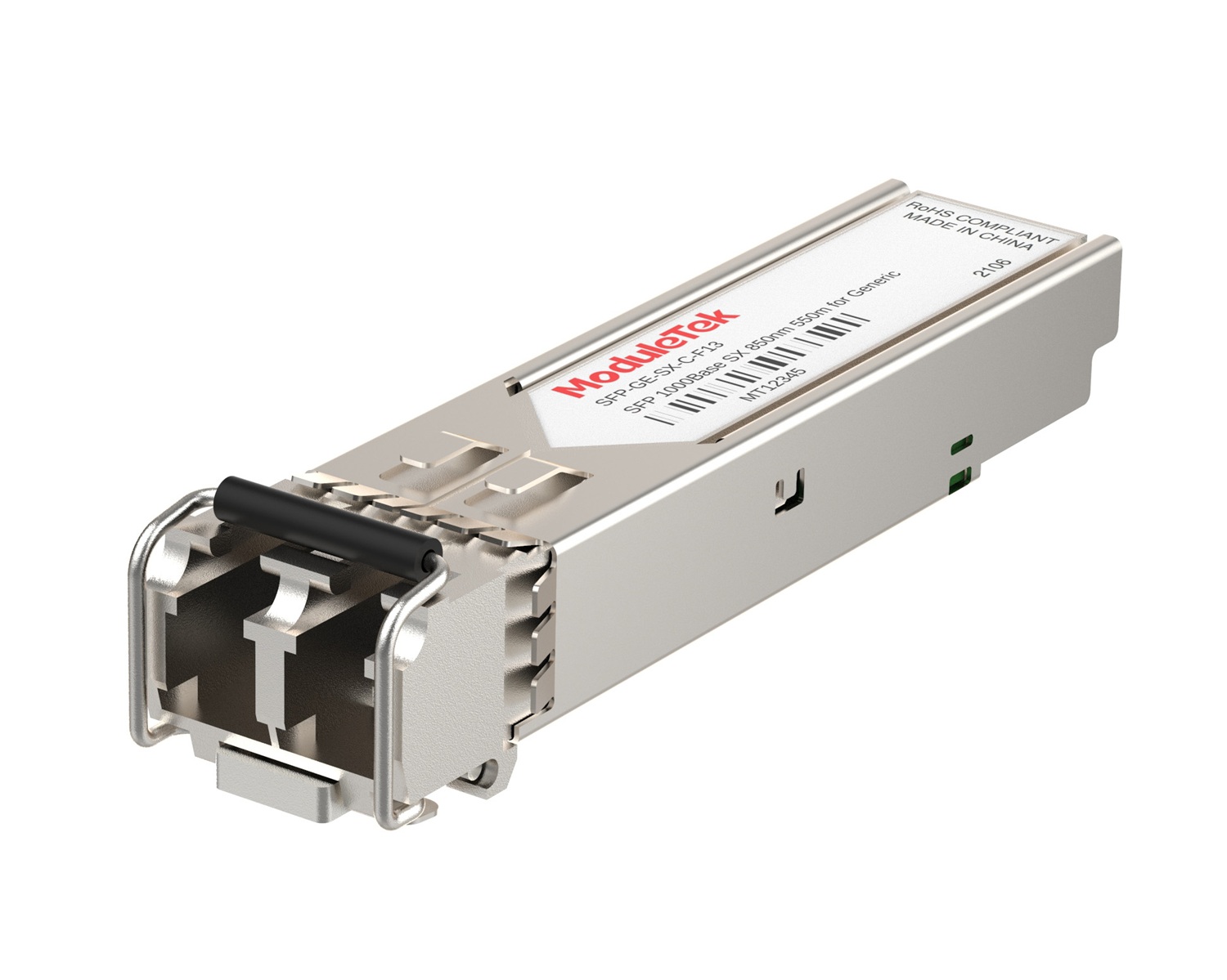 1G Optical Transceivers
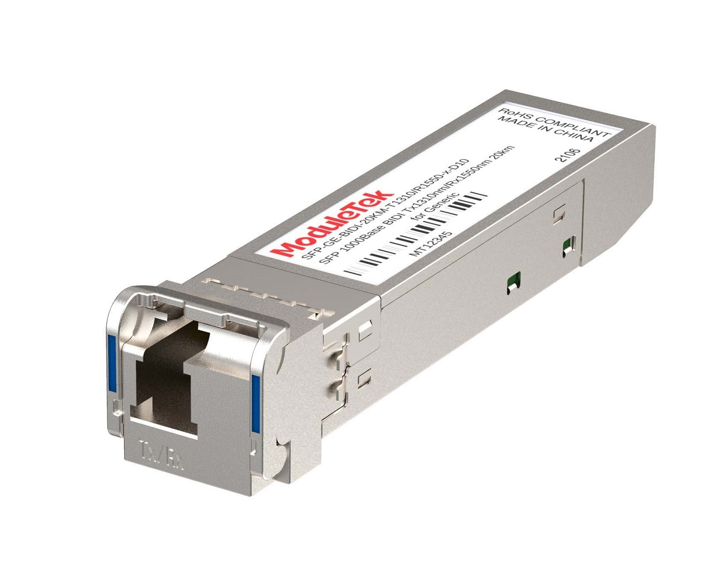 1G BIDI Optical Transceivers
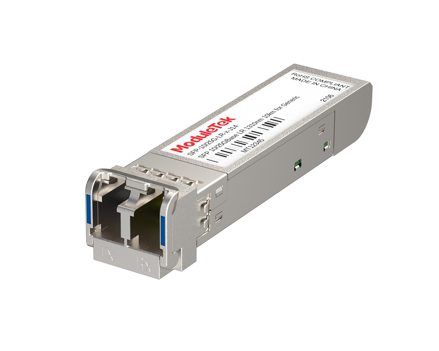 Dual-Rate Optical Transceivers
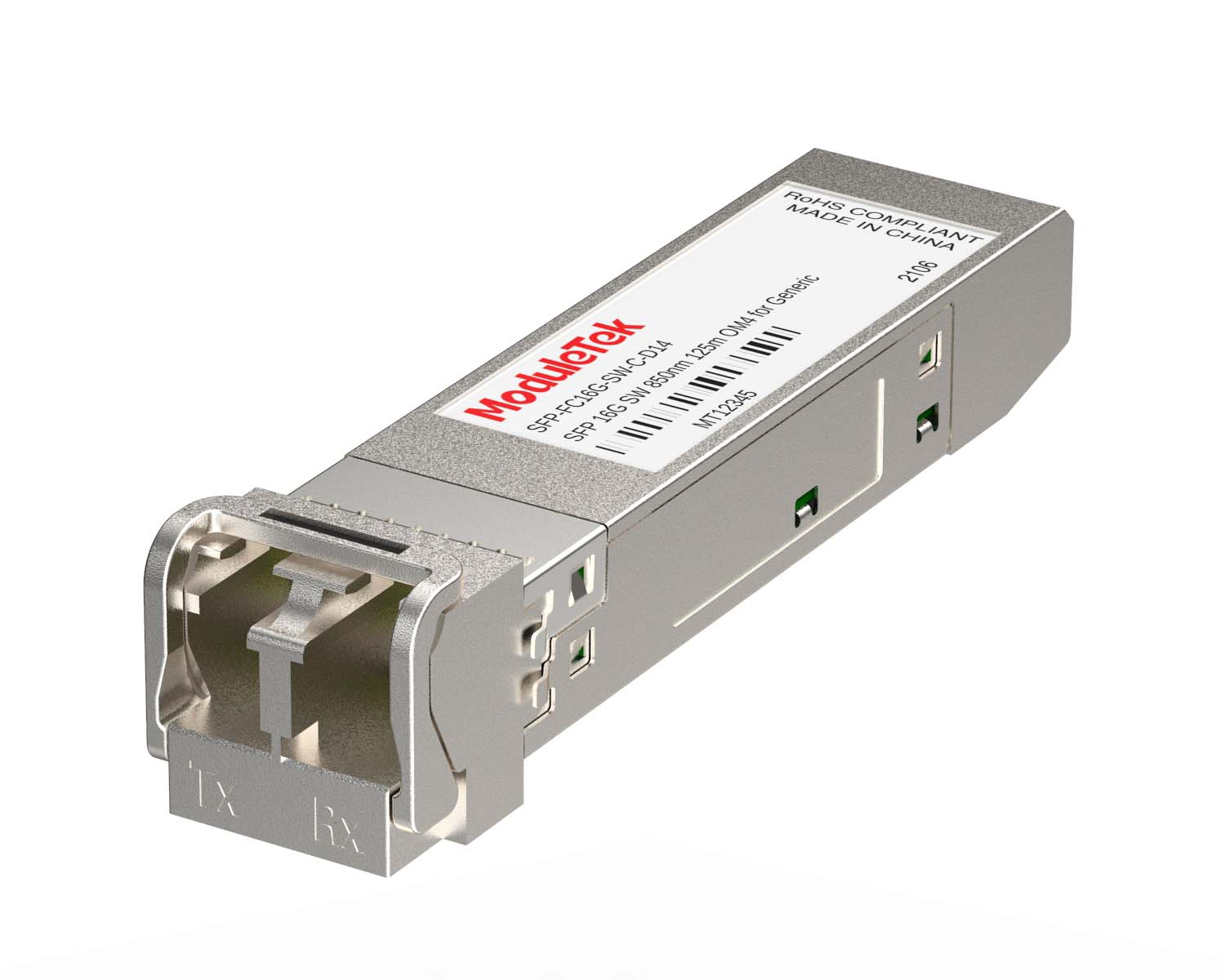 FC 16G/32G Optical Transceivers
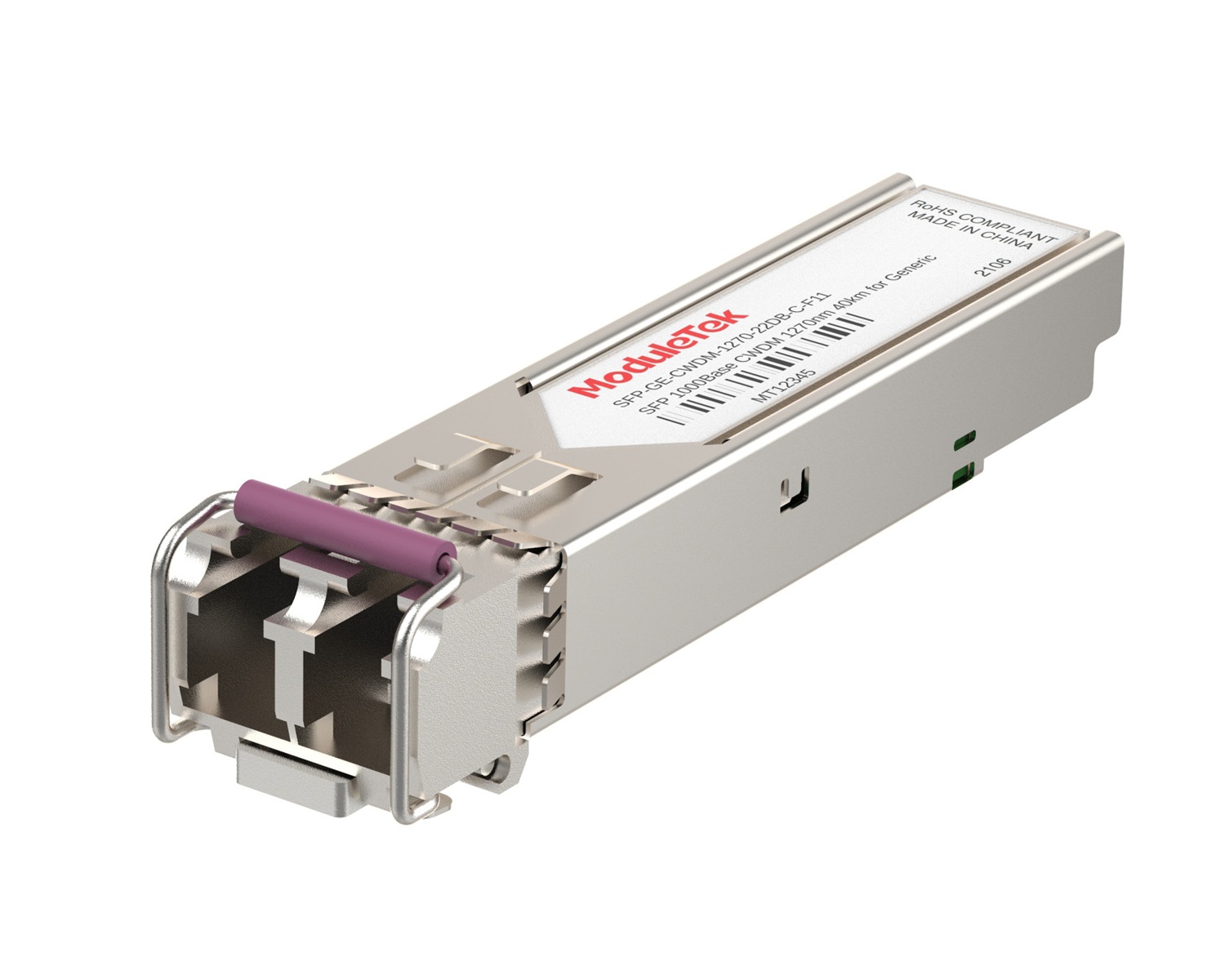 CWDM Optical Transceivers
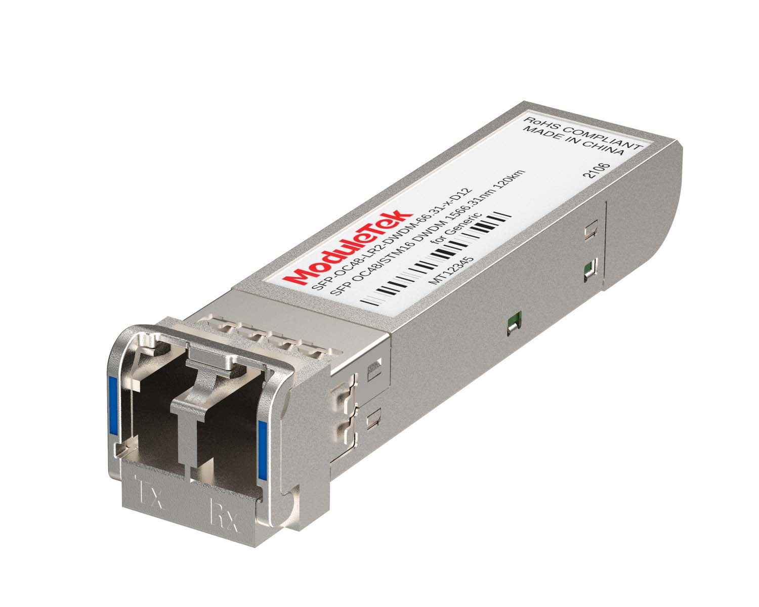 DWDM Optical Transceivers
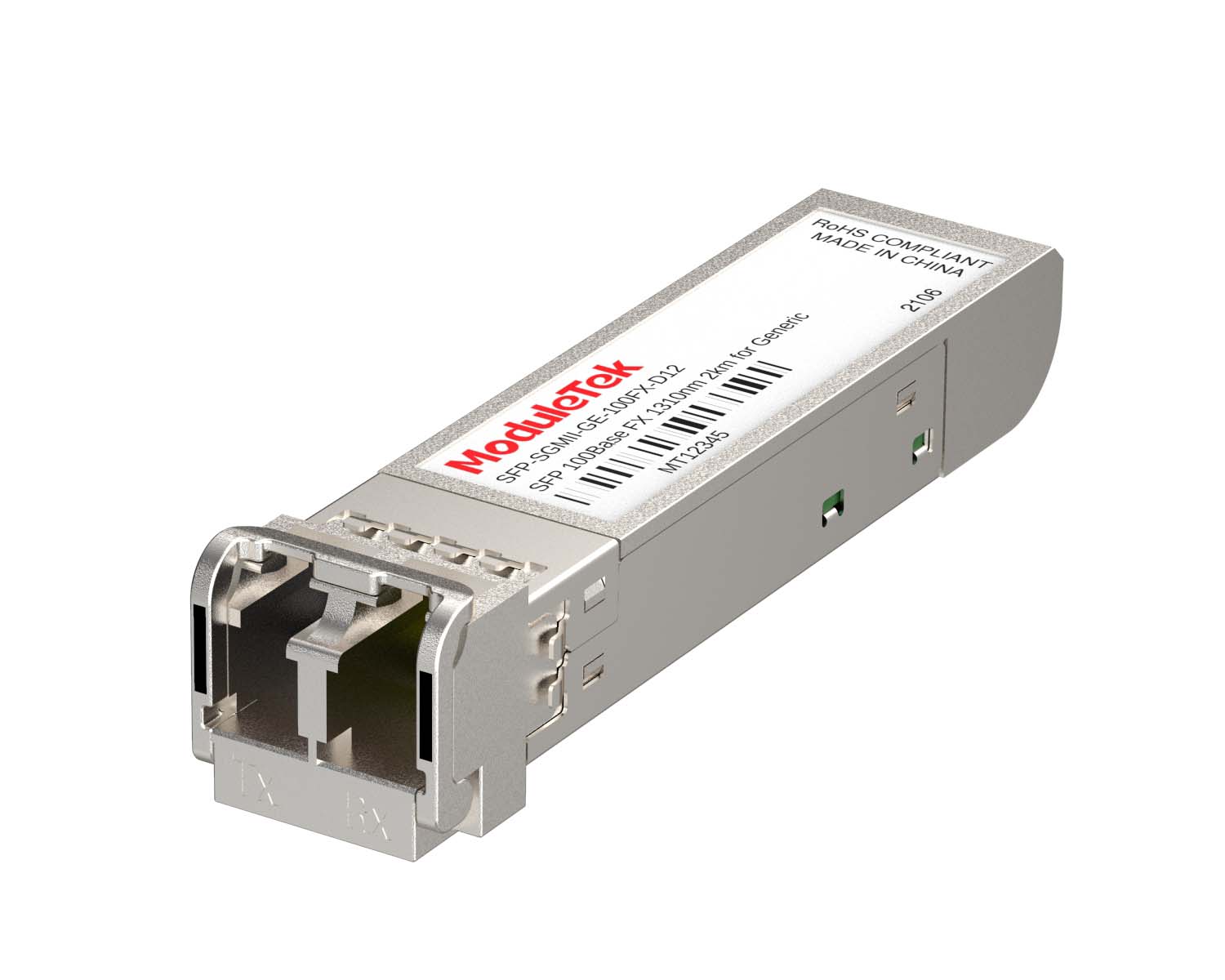 SGMII Port Optical Transceivers
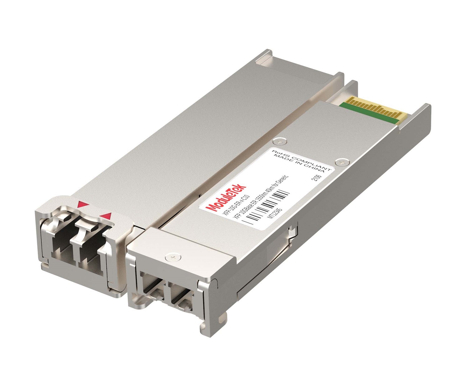 XFP Optical Transceivers
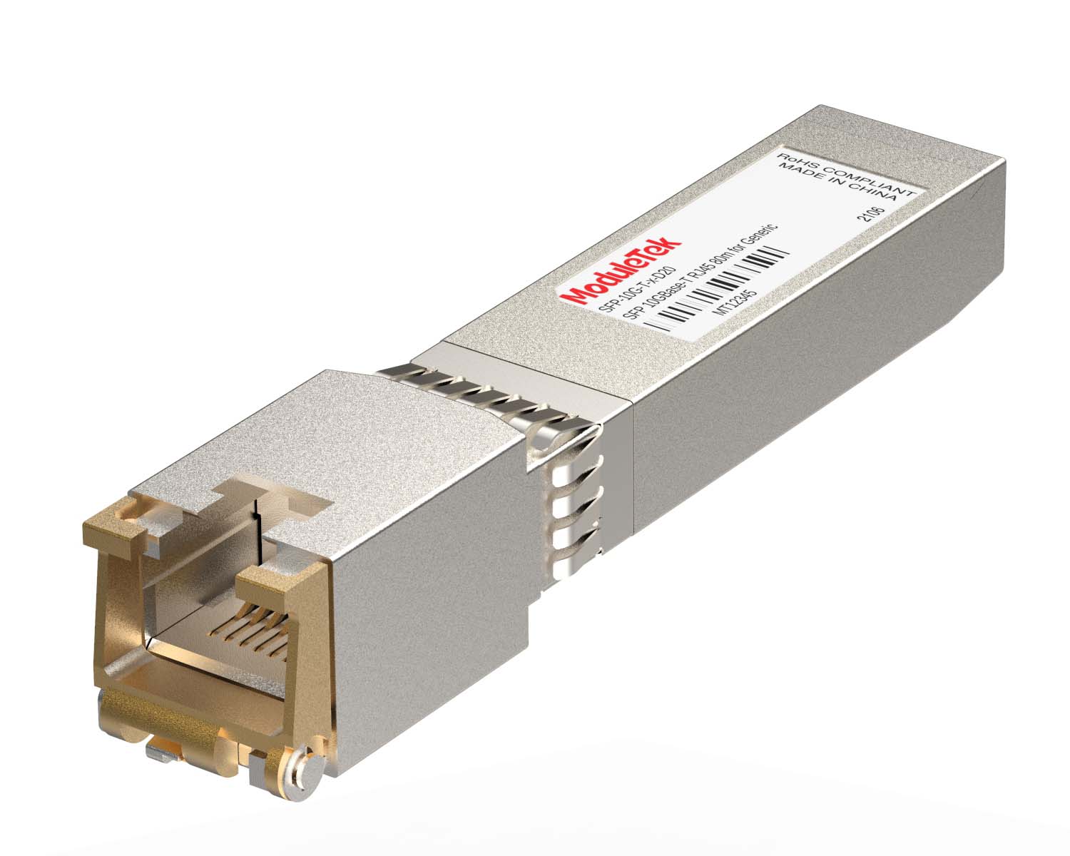 100M/1G/10G Coppers
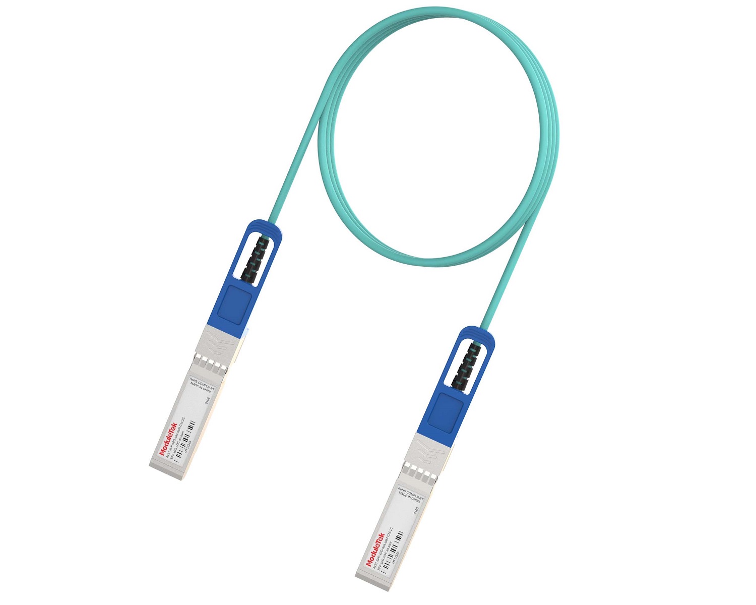 Full-Rate AOC & Breakout Series
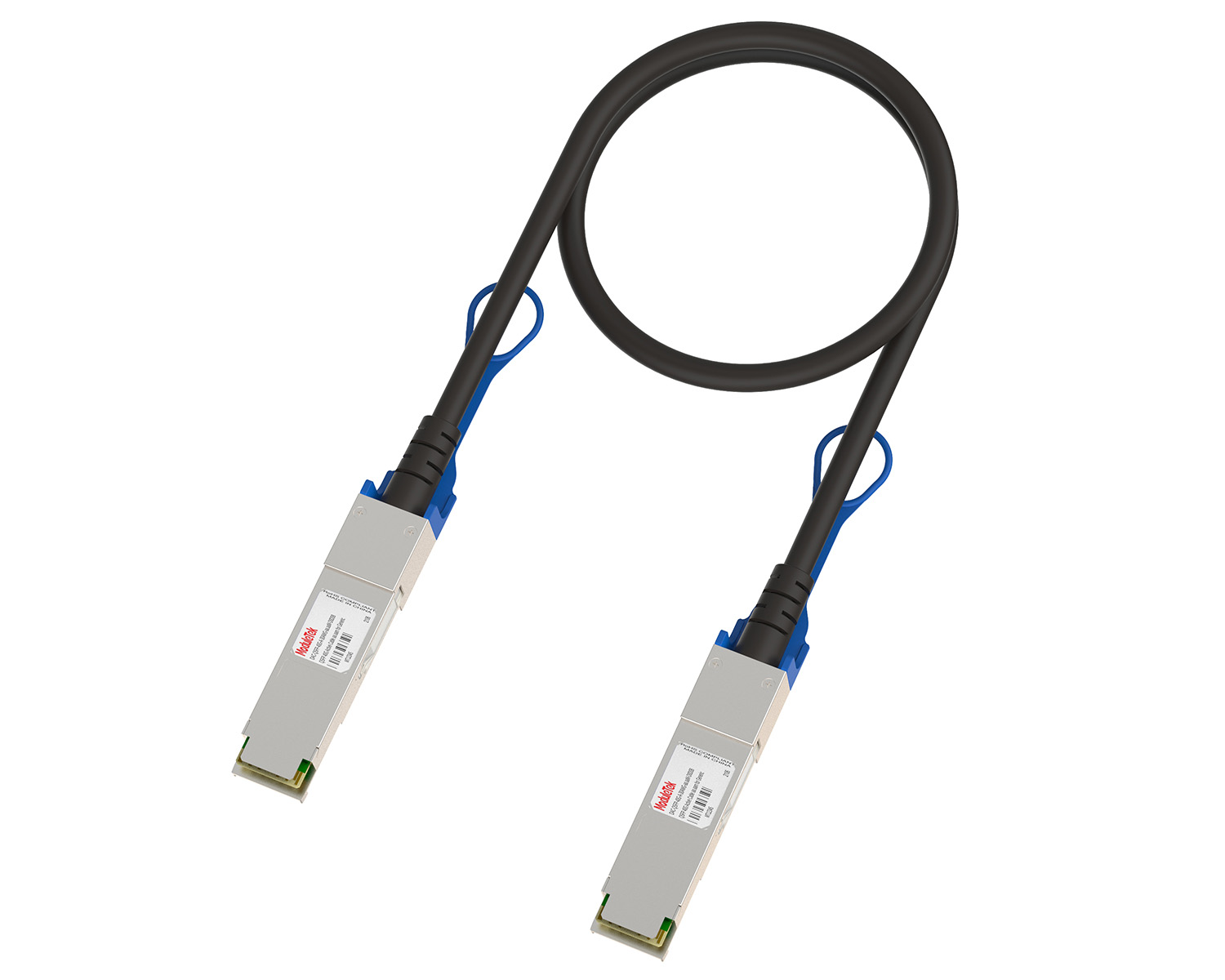 10G/40G Active DAC Series
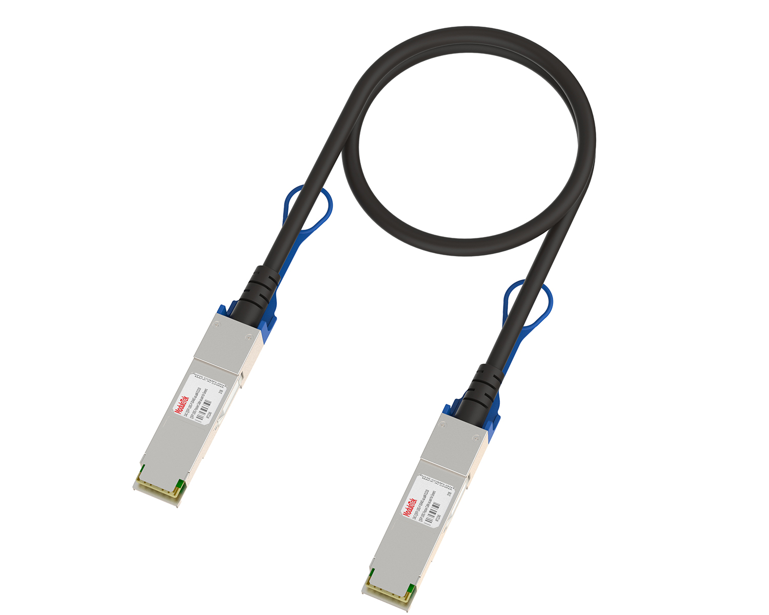 Full-Rate Passive DAC Series
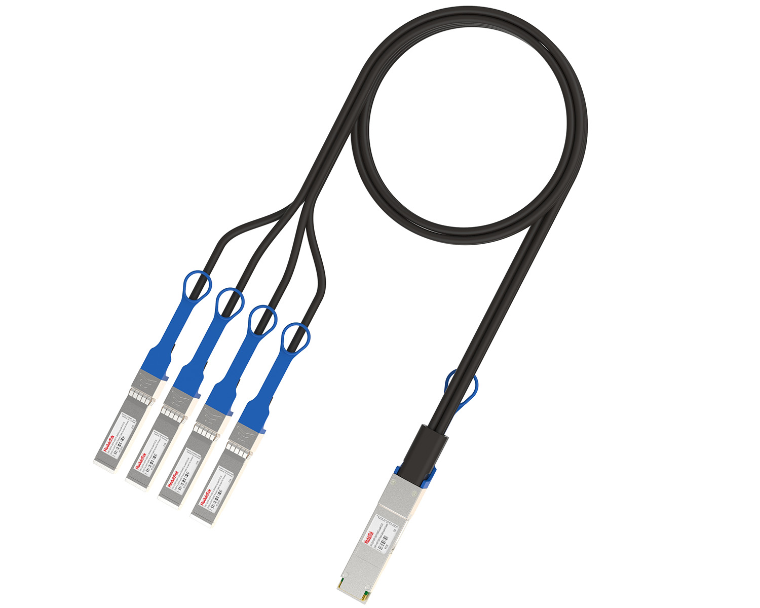 40G/100G Passive Breakout DAC Series
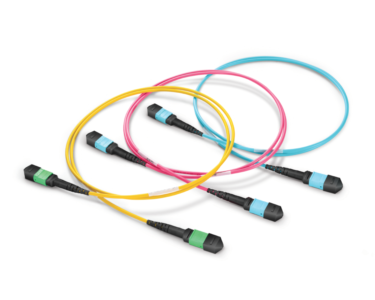 Regular/MTP-MPO Fiber Patch Cords
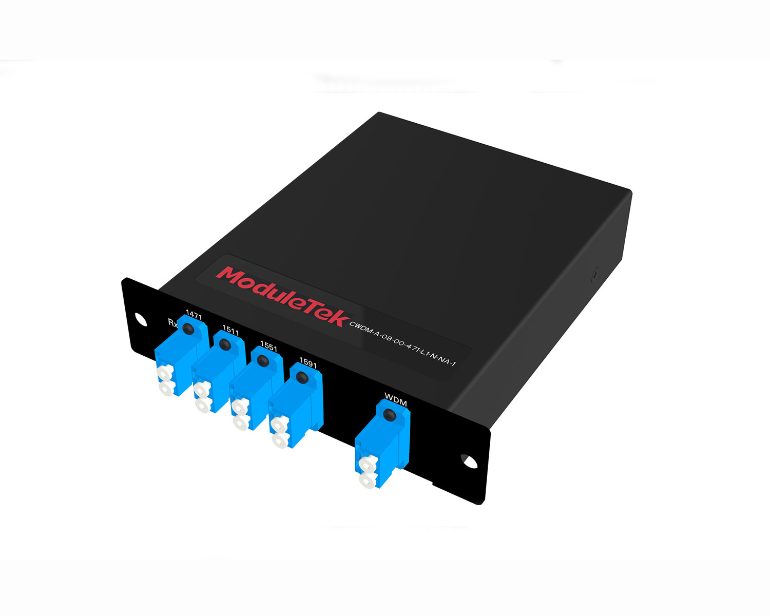 MT2011
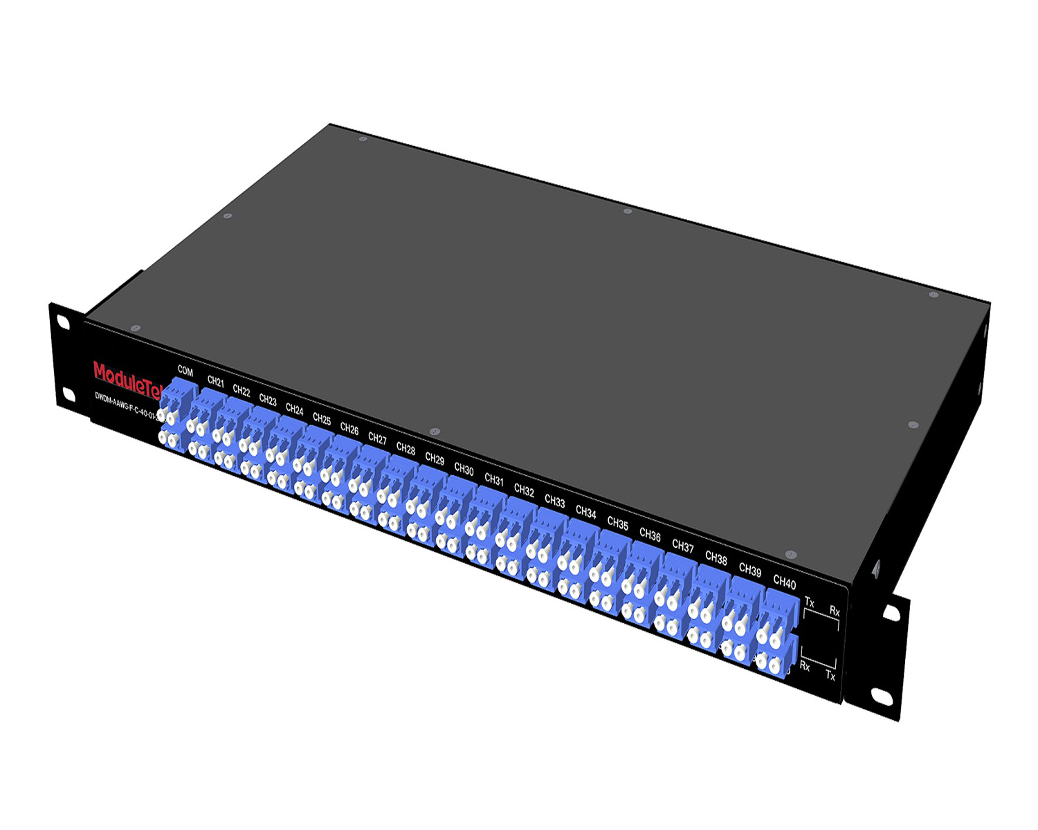 MT2010
 CodingBox
 QSFP to SFP Adapter
Showcase Of RAISECOM ISCOM2624GF-4C-HI-AC Switch
Time: 2024-01-16
Moduletek Laboratory introduces the RAISECOM ISCOM2624GF-4C-HI-AC switch, showcasing its appearance, system configuration, and internal structure in detail.
1. Product Overview
The front panel of the RAISECOM ISCOM2624GF-4C-HI-AC switch is equipped with 24× 1G SFP ports, 4× 10G SFP+ ports, 4× RJ45 combo ports, 1× RJ45 console port, 1× out-of-band management port, and 1× AC power jack. The rear panel is fitted with 1× DC power port.
Official key parameters and physical appearance are as follows:
Table 1 Official Device Specifications
|
Attributes
|
Parameters
|
|
Device Model
|
ISCOM2624GF-4C-HI
|
|
Interface Format
|
Uplink:4*10G SFP+
Downlink: 24*GE SFP(four Combo ports)
|
|
Dimensions (W*D*H)
|
440mmx220mmx43.6mm
|
|
Power
|
Supply AC DC
AC:220V DC:-48V
|
|
Operating Temperature
|
0℃~50℃
|
|
Maintenance
|
Support SNMPv1/v2c/v3, support network management system
Support WEB network management
Support system log, hierarchical alarm
Support hardware monitoring, optical module digital diagnosis
Supports IEEE802.3ah, IEEE802.1ag OAM.
Support IPv6 address management
|
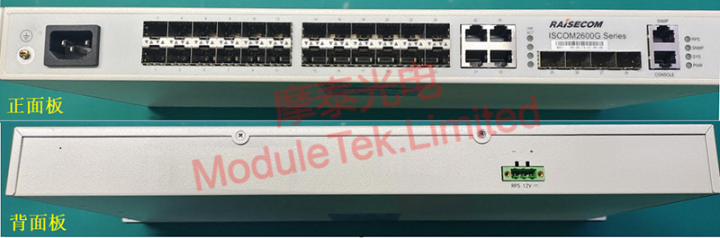
Figure 1 Front & Rear Panels
2. Console Login
Connect the power cord to power on the switch. Use the included RJ45-to-DB9F dedicated console cable to connect a PC to the switch via the serial port.
Default console parameters:
• Baud rate: 9600
• Default username: raisecom
• Default password: raisecom
After login, you will access the device console.
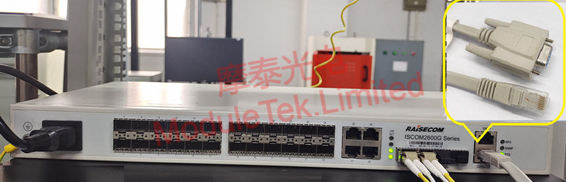
Figure 2 Device Power-On Status
The 4× 10G SFP+ ports support backward compatibility with 1G rates; you can switch the interface rate in interface configuration mode.
When a Moduletek SFP-GE-SX optical module is installed into the switch with a fiber jumper connected, the module achieves normal LINK status, and the port indicator lights up. The switch can correctly identify module information, including module type, vendor name, serial number, wavelength, and transmission distance. DOM data is readable, and all values are within the threshold range with no alarms.
Table 2 Optical Module Information
|
Item
|
Information Read by Switch
|
|
LINK
|
|
|
Identification
|
|
|
DOM Data
|
|
3. Device Teardown
After removing the top cover of the switch, the internal structure is divided into two main parts:
• A main PCB integrating core chips, resistors, and heat sinks
• A power supply module, including a DC power board and an AC power board
Two cooling fans are independently mounted on one side.
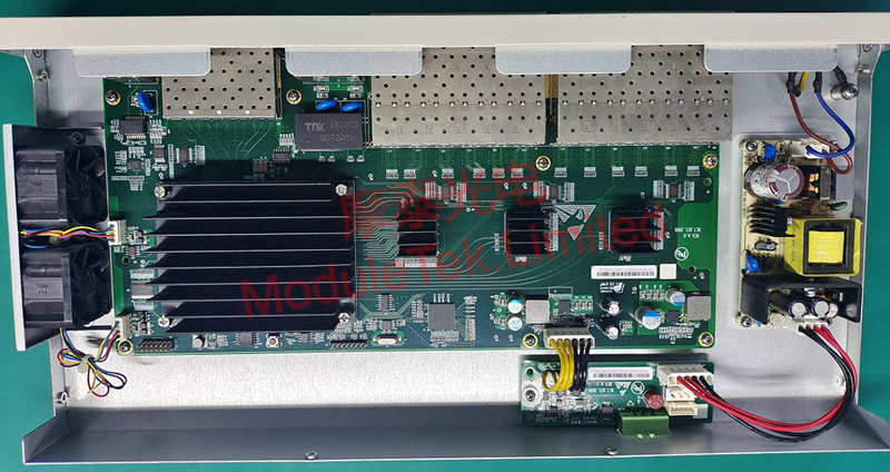
Figure 3 Internal Structure
After removing the heat sink, the main switch chip is exposed: Broadcom BCM56151A0KFSBG.
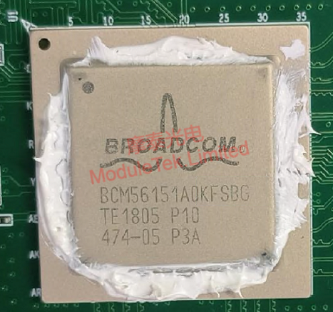
Figure 4 Main Switch Chip
Moduletek optical modules are fully compatible with RAISECOM networking devices. Welcome to inquire and place orders.
For further inquiries about the above content, please contact us at: sales@moduletek.com


