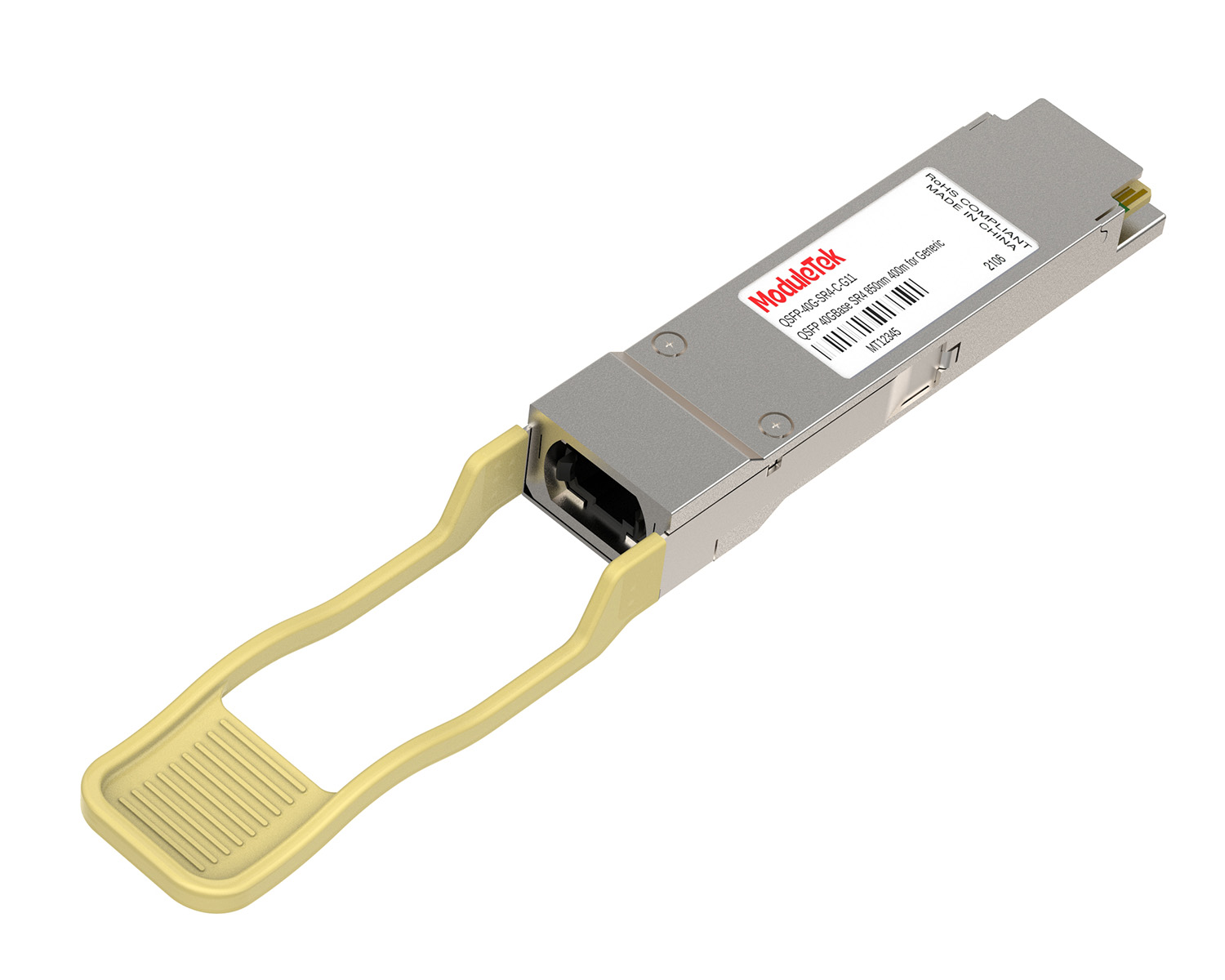
 40G/100G Optical Transceivers
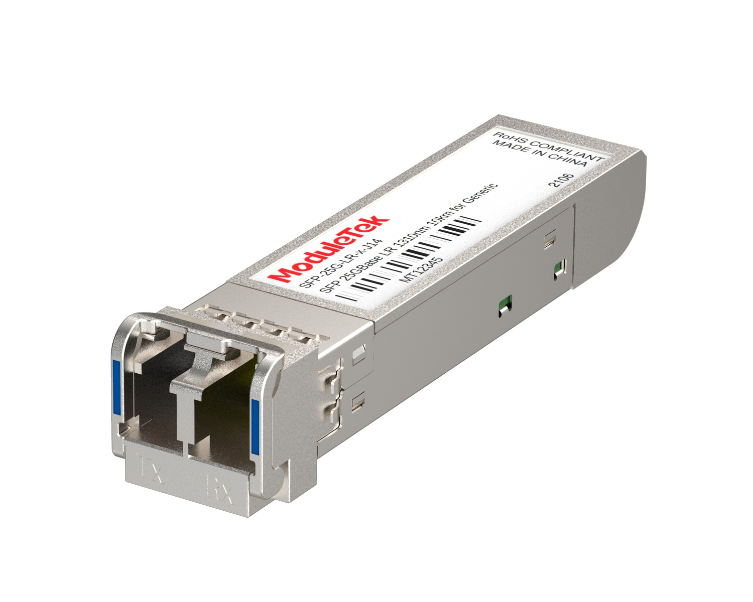 25G Optical Transceivers
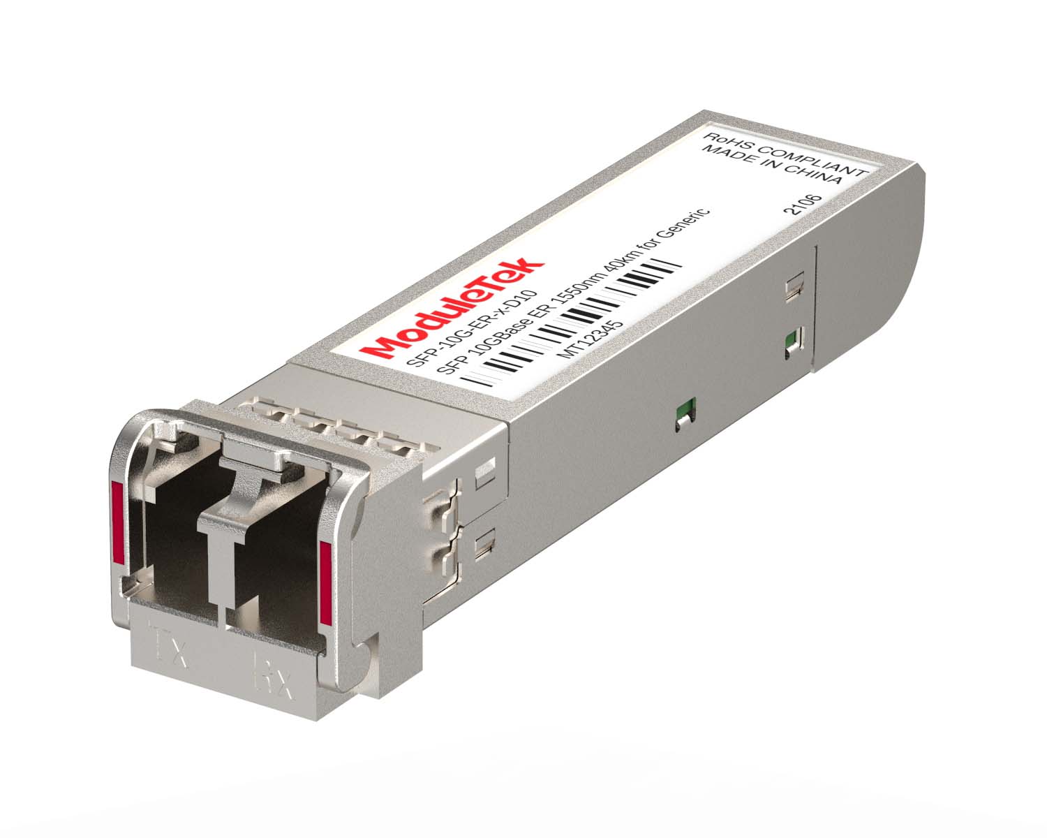 10G Optical Transceivers
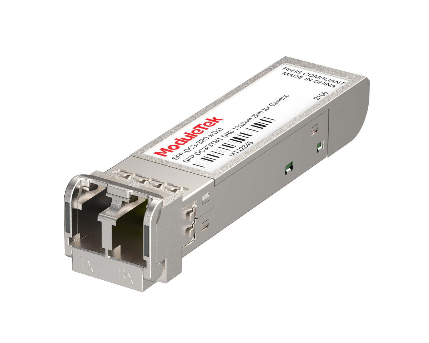 155M/2.5G Optical Transceivers
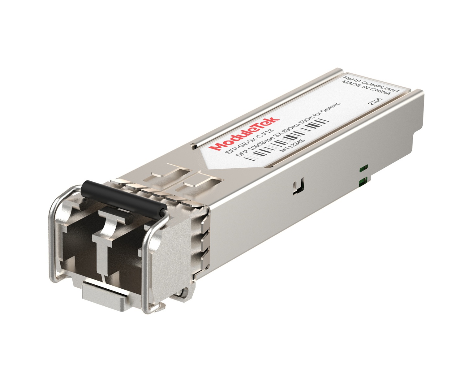 1G Optical Transceivers
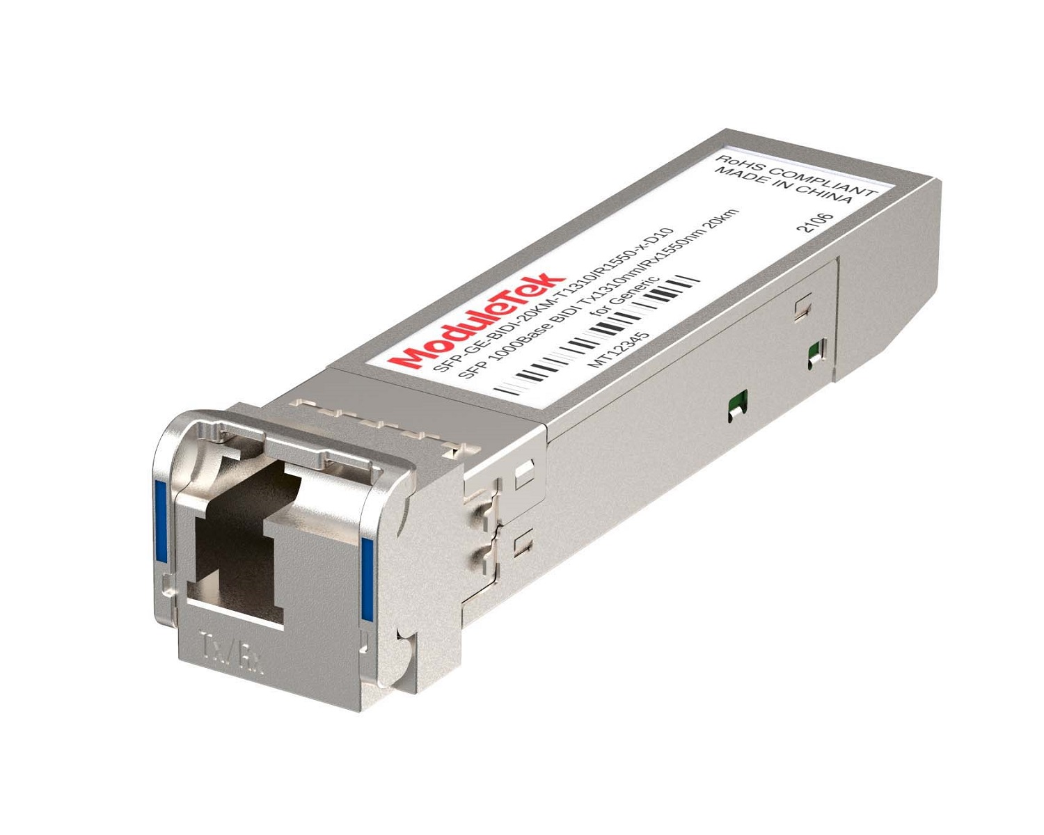 1G BIDI Optical Transceivers
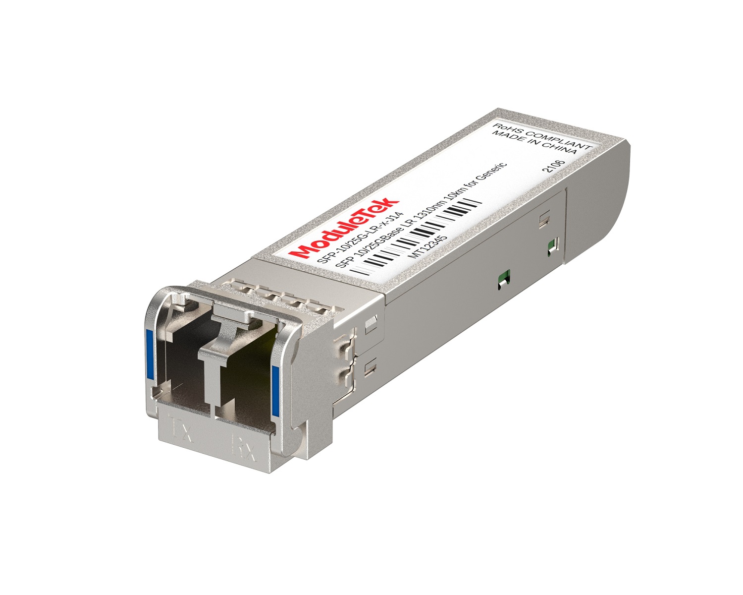 Dual-Rate Optical Transceivers
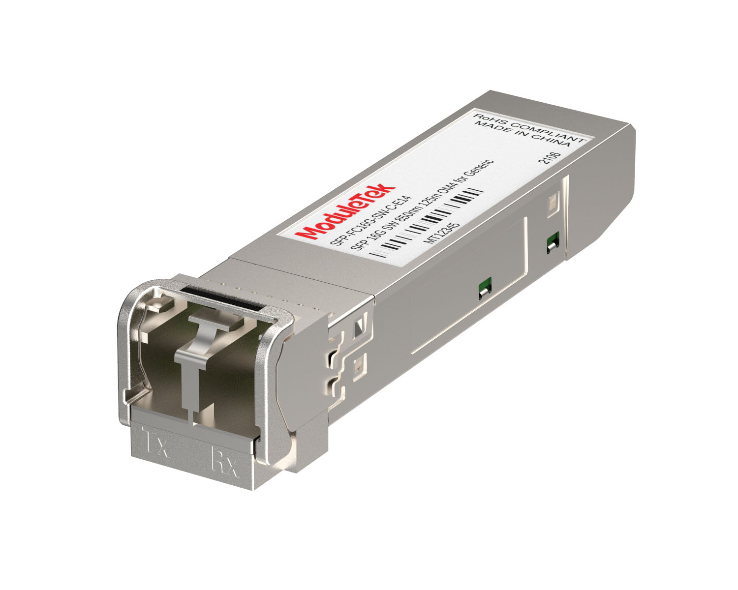 FC 16G/32G Optical Transceivers
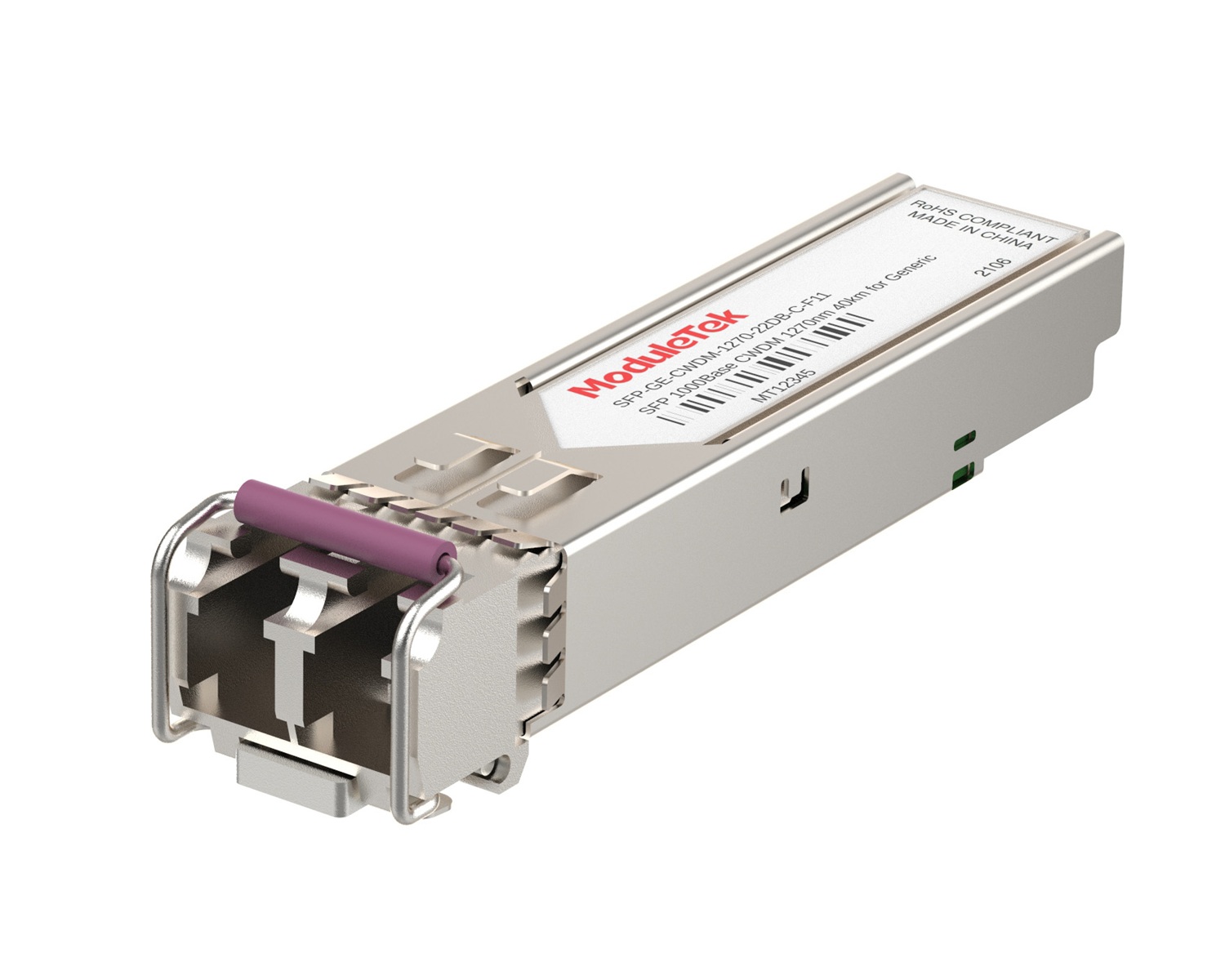 CWDM Optical Transceivers
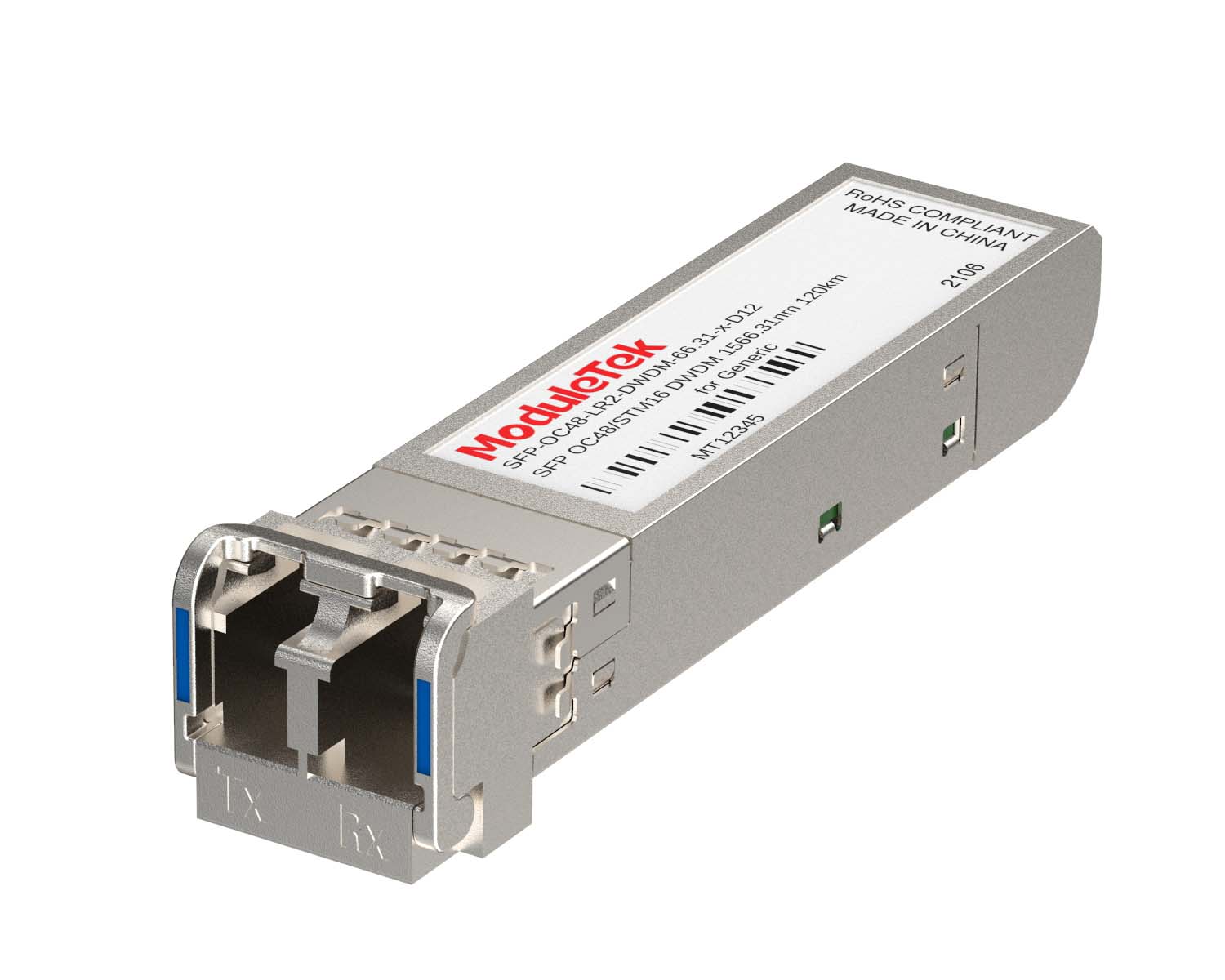 DWDM Optical Transceivers
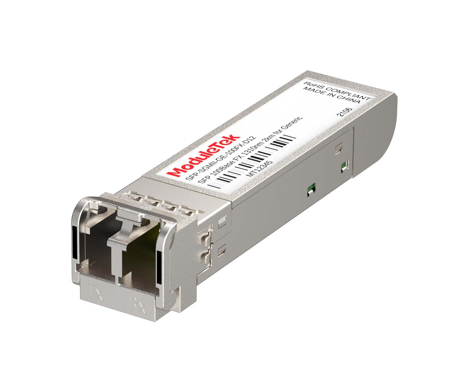 SGMII Port Optical Transceivers
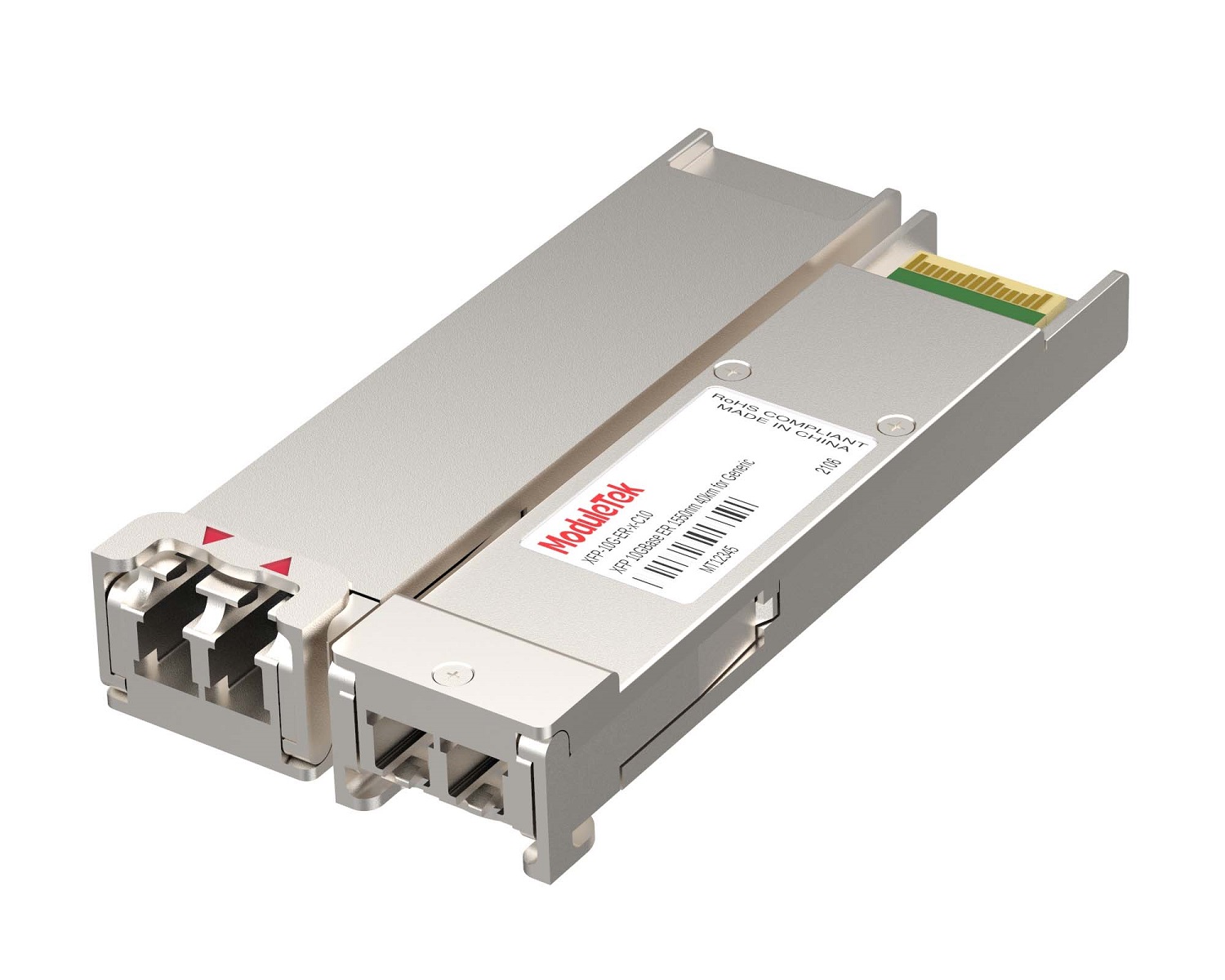 XFP Optical Transceivers
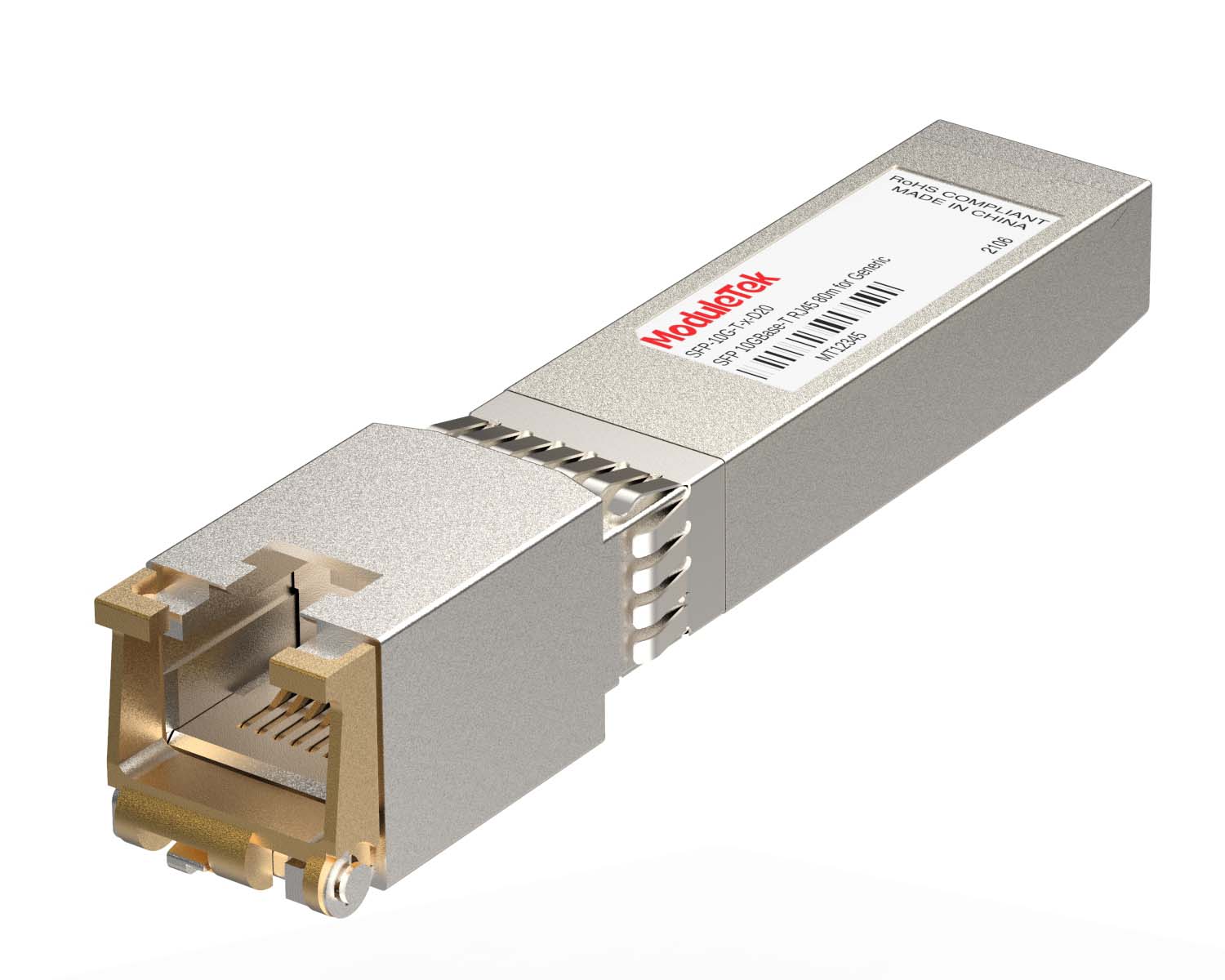 100M/1G/10G Coppers
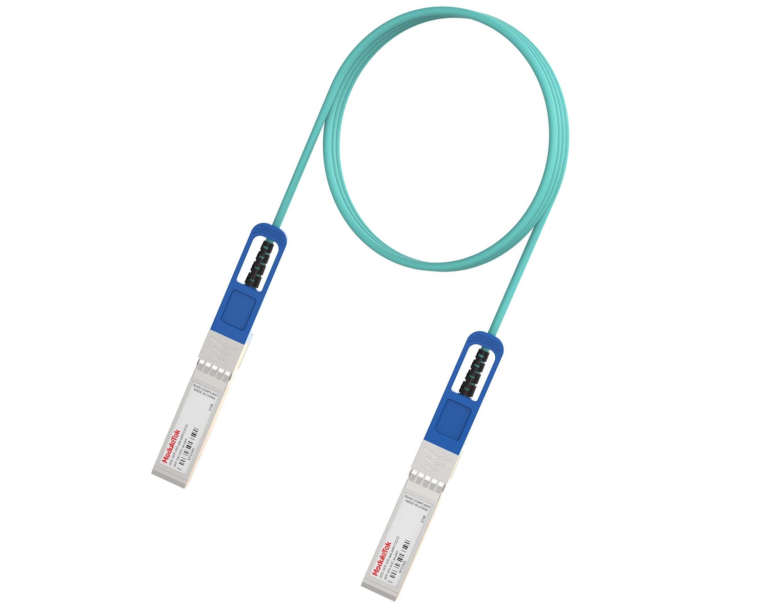 Full-Rate AOC & Breakout Series
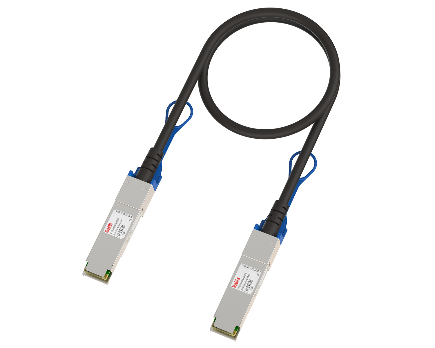 10G/40G Active DAC Series
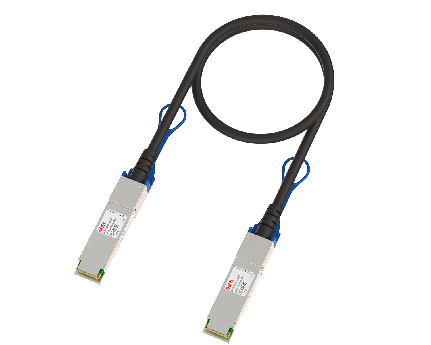 Full-Rate Passive DAC Series
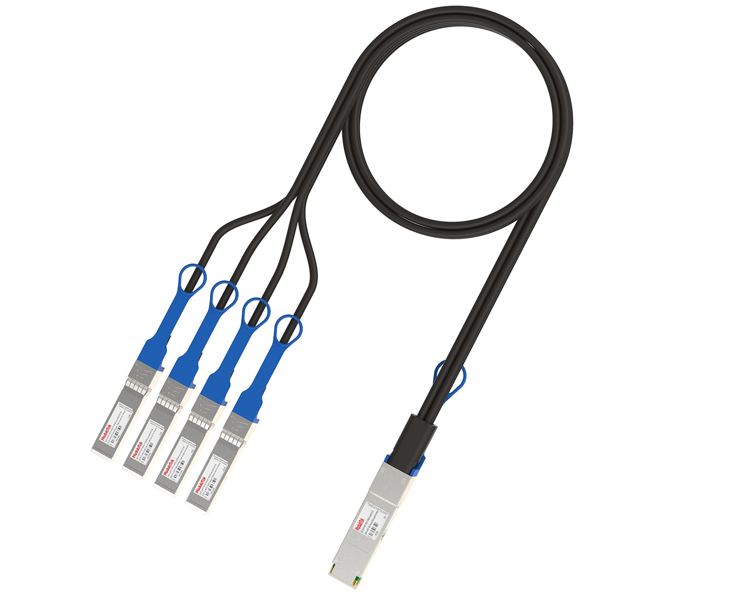 40G/100G Passive Breakout DAC Series
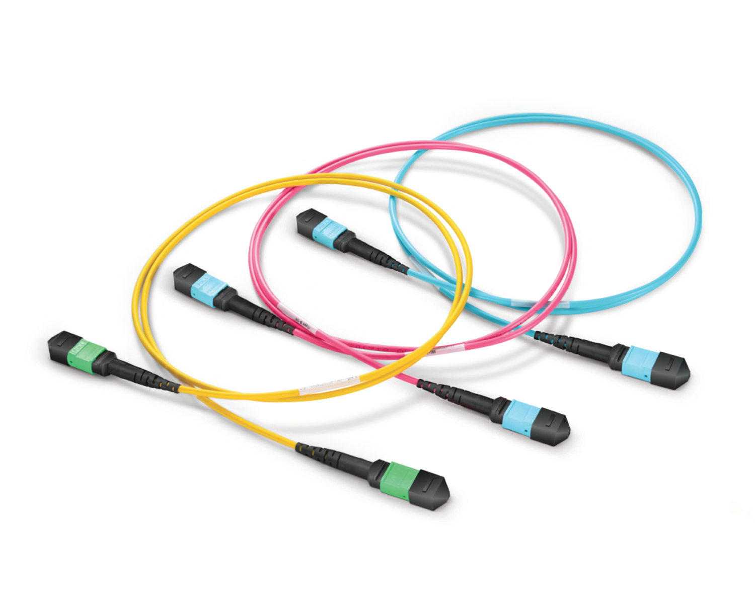 Regular/MTP-MPO Fiber Patch Cords
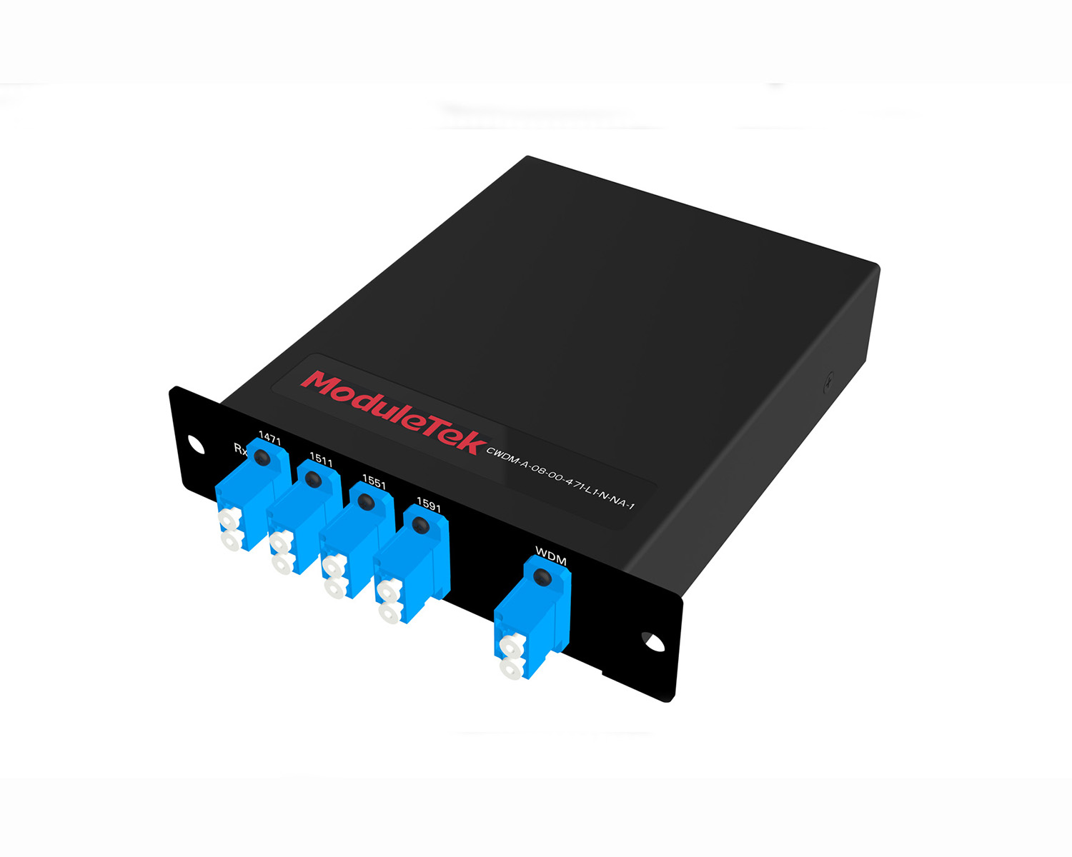 MT2011
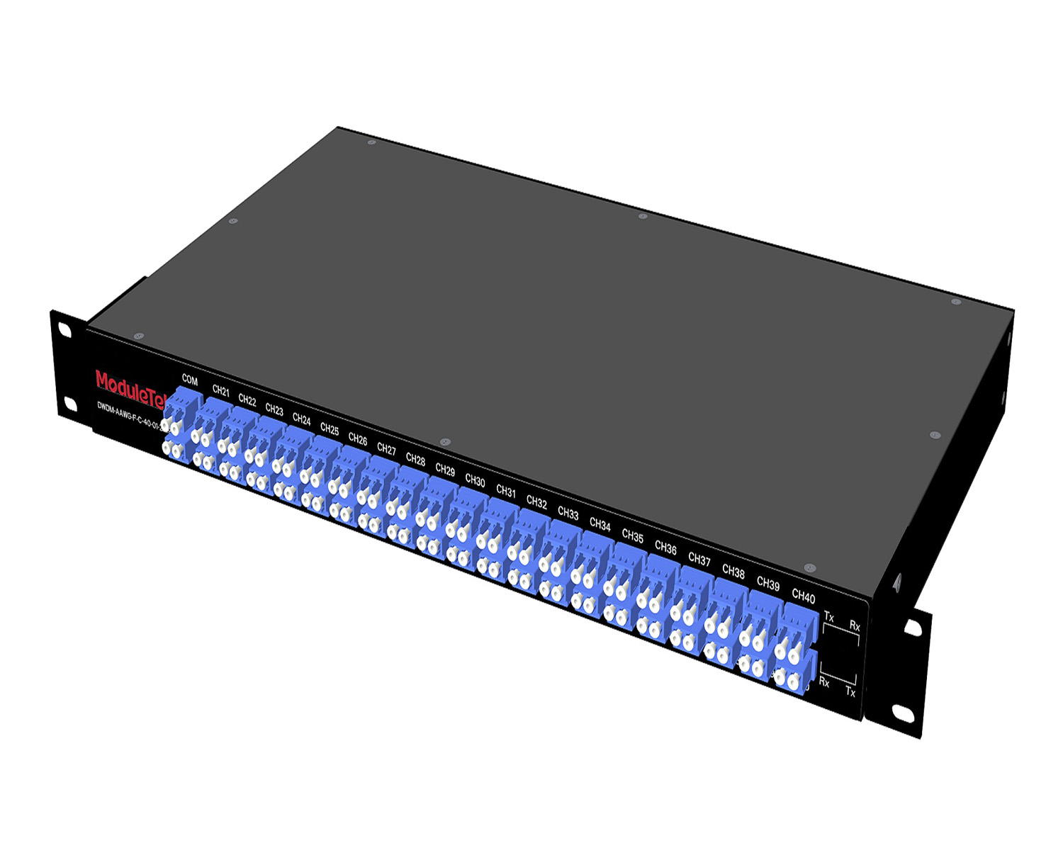 MT2010
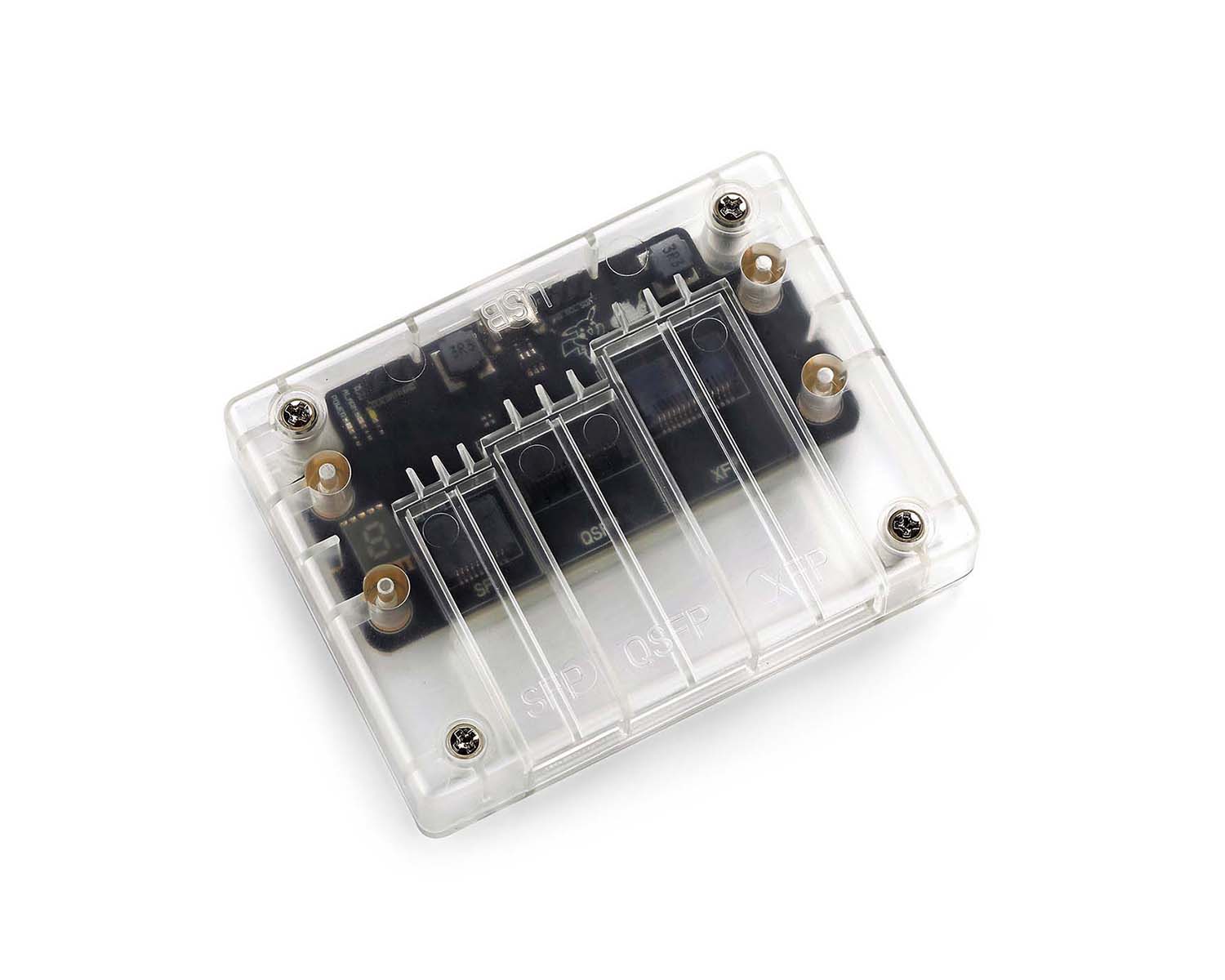 CodingBox
 QSFP to SFP Adapter
Nokia 7250 IXR-E Switch Unboxing
Time: 2024-01-26
Moduletek Laboratory purchased a Nokia 7250 IXR-e switch (model: 3HE14782AA, 24SFP+ 8SFP28 2QSFP28) to test our 10G/25G SFP and 100G QSFP module series. Below is a complete unboxing and acceptance overview.
Table 1 Official Device Specifications
|
Feature
|
7250 IXR-e 2QSFP28 8SFP28 24SFP+ (4 variants)
|
|
Service interfaces
|
· 2×QSFP28100GE
· 8×SFP28 / SFP+ / SFP 25/10/1GE²
· 24×SFP+ / SFP 10/1GE
|
|
Control interfaces
|
Console, management, USB, 1PPS out, SD slot, reset button
|
|
Satellite Mode option
|
Supported
|
|
Power supply options
|
· Two feeds:Modular AC or DC power supplies
· Supports concurrent use of AC and DC power supplies
|
|
Power requirements
|
· AC input (rated) : 100 V to 240 V, 50 Hz to 60 Hz
· Dcinput (rated) : 24V DC/-48 V DC
|
|
Normal operating
Temperature range
|
-40℃ to + 65℃( -40°F to + 149°F ) sustained
|
|
Note:² GE on SFP28 ports is a future software deliverable
|
|
The package includes: 1× switch chassis, 1× SD card, 2× 20–60V DC power modules. No additional accessories are provided.
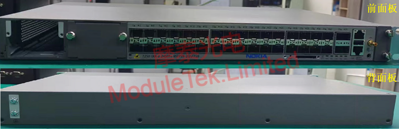
Figure 1 Front and Rear Panels of the Switch
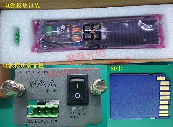
Figure 2 Accessories in the Package
The front panel includes: 24× 10G SFP+ ports, 8× 25G SFP28 ports, 2× 100G QSFP28 ports, 2× power module slots, 1× SD card slot, 1× RJ45 console port, 1× out-of-band management port, and 1× USB port.
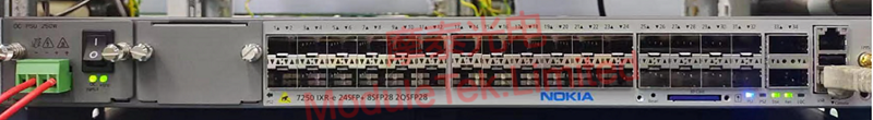
Figure 3 Power-On Status of the Switch
To log in via the console:
Connect a PC to the switch using an RJ45-to-DB9 console cable.
Default console parameters:
• Baud rate: 115200
• Username: admin
• Password: admin
To view the device model and firmware version, run:
show version
All interfaces are administratively disabled by default.
To enable an interface, enter global configuration mode in MD-CLI and run:
port <port_number> admin-state enable
Once enabled, the port indicator turns orange and blinks.
Note: <port_number> represents the physical interface number. To list all ports, run:
show port
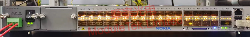
Figure 4 Interface with Blinking Orange Indicator
When a Moduletek SFP-25G-SR optical module is installed with a fiber jumper connected, the module establishes a normal LINK, and the port indicator lights green.
The switch correctly identifies module details including type, serial number, wavelength and transmission distance. DOM data can be read normally and stays within the normal threshold range without alarms.
Note: To view detailed interface, module and DOM information, run:
show port <port_number>
Table 2 Optical Module Information Read by the Switch
|
Item
|
Information Read by Switch
|
|
LINK
|
|
|
Identification
|
|
|
DOM Data
|
|
Moduletek optical modules are fully compatible with Nokia switching devices. Welcome to inquire and place orders.
For further inquiries about the above content, please contact us at: sales@moduletek.com


