 40G/100G Optical Transceivers
 25G Optical Transceivers
 10G Optical Transceivers
 155M/2.5G Optical Transceivers
 1G Optical Transceivers
 1G BIDI Optical Transceivers
 Dual-Rate Optical Transceivers
 FC 16G/32G Optical Transceivers
 CWDM Optical Transceivers
 DWDM Optical Transceivers
 SGMII Port Optical Transceivers
 XFP Optical Transceivers
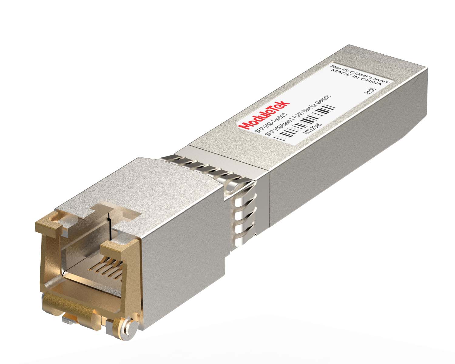 100M/1G/10G Coppers
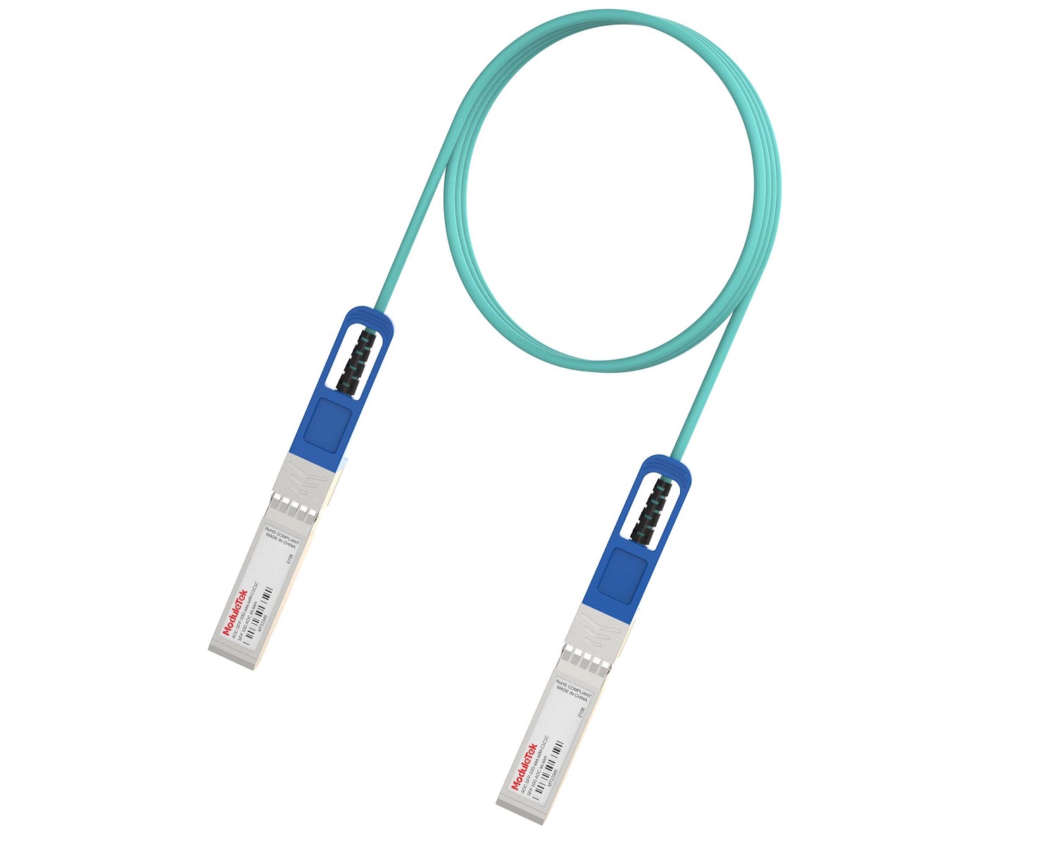 Full-Rate AOC & Breakout Series
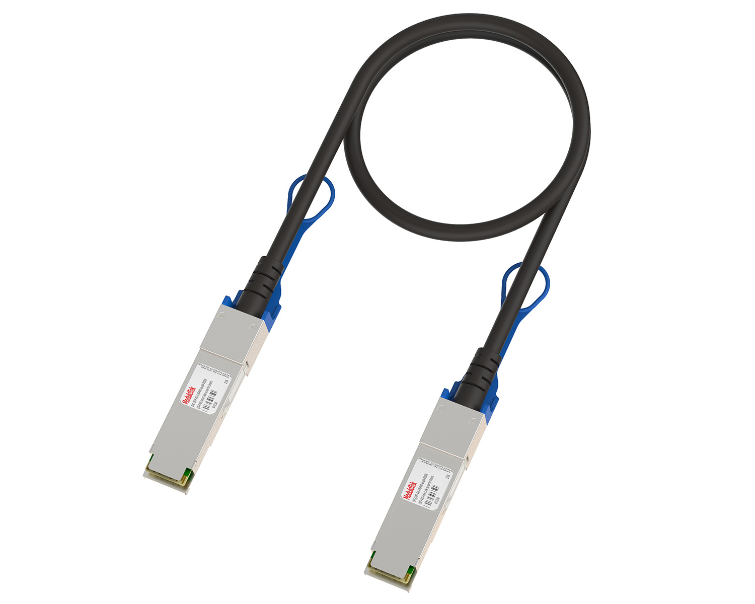 10G/40G Active DAC Series
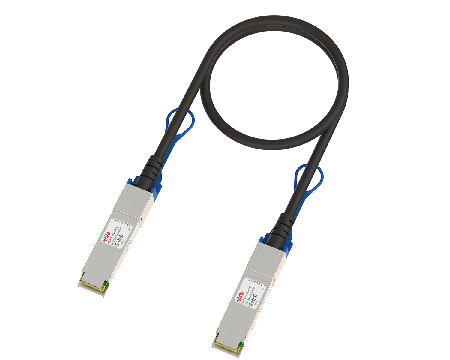 Full-Rate Passive DAC Series
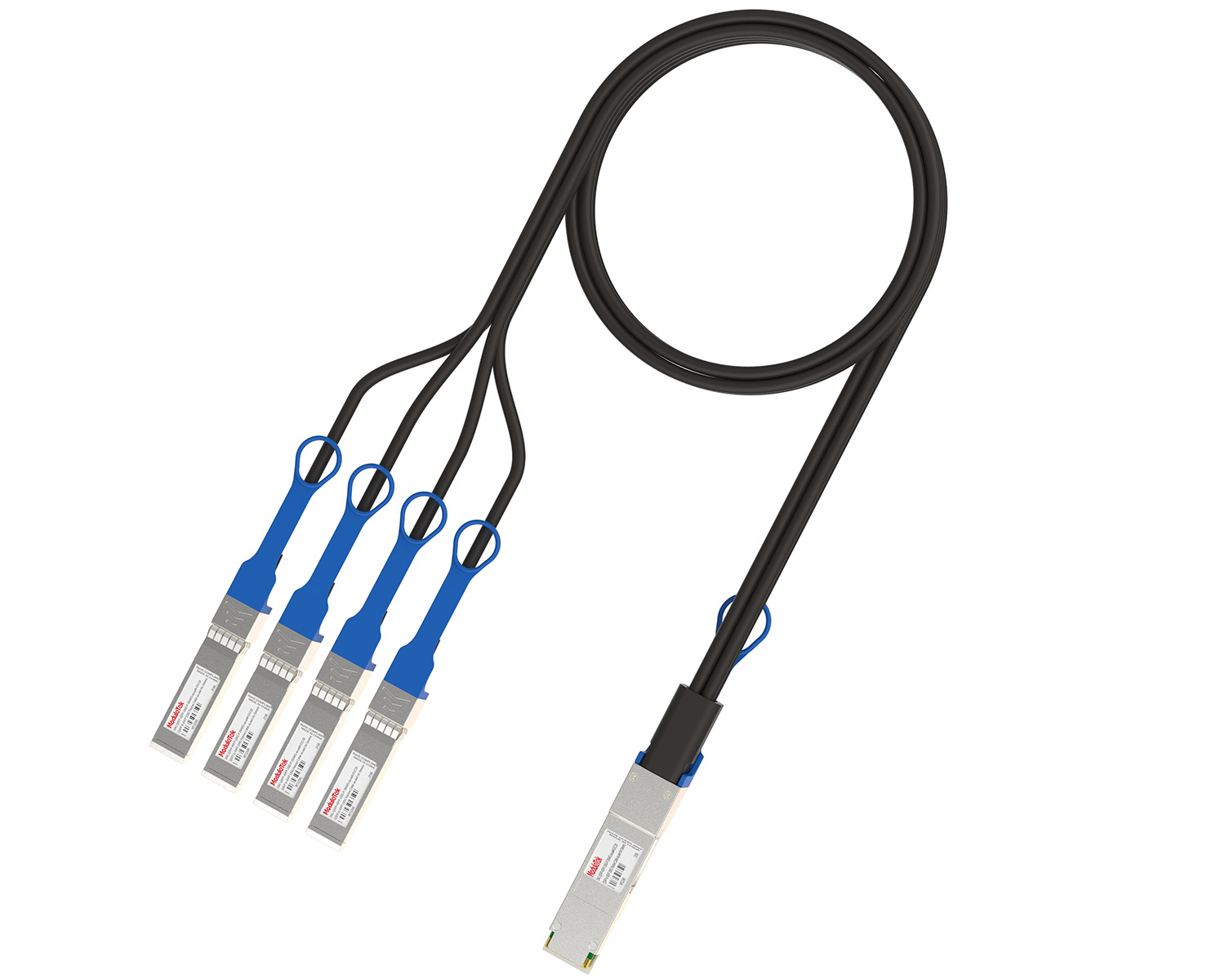 40G/100G Passive Breakout DAC Series
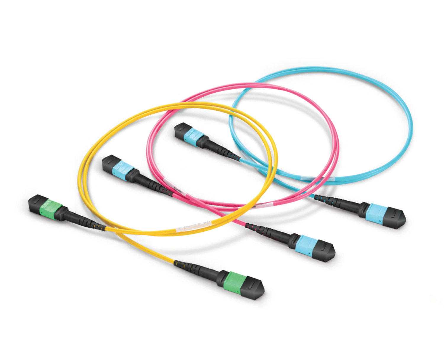 Regular/MTP-MPO Fiber Patch Cords
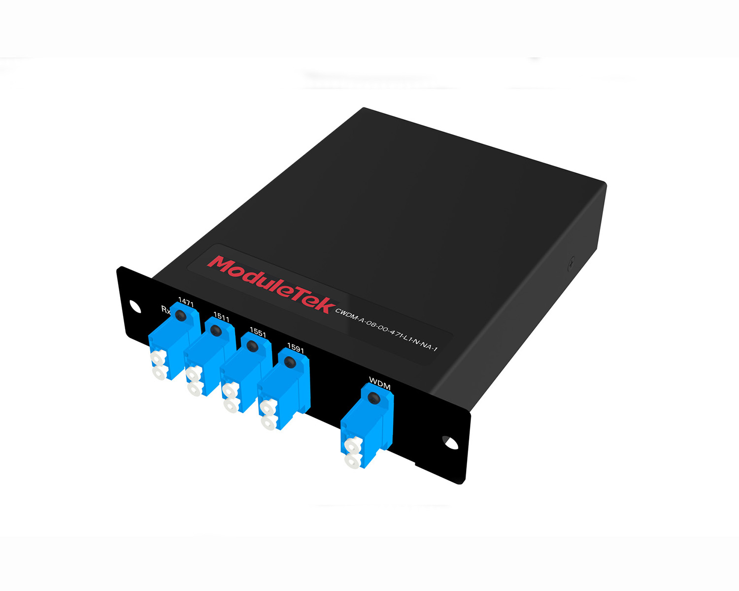 MT2011
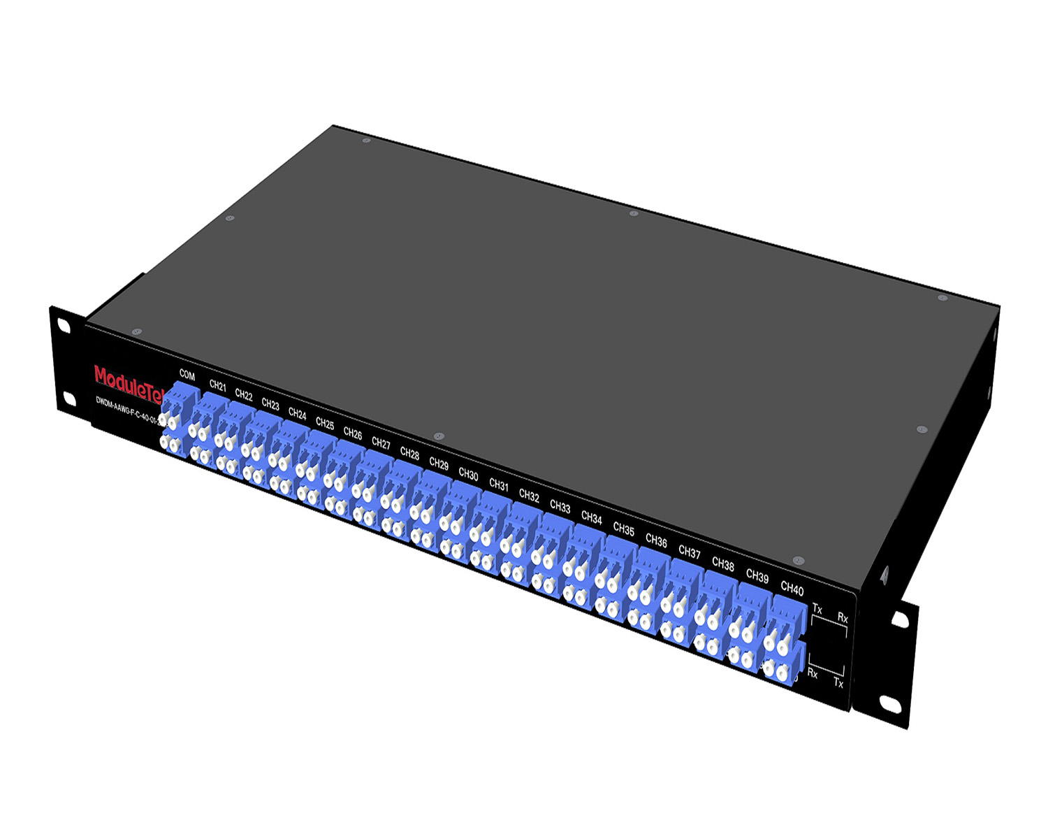 MT2010
 CodingBox
 QSFP to SFP Adapter
Palo Alto Firewall IP Configuration Method
Time: 2025-03-25
While configuring interface IP addresses for the Palo Alto PA-850 and PA-3060 firewalls, Moduletek Laboratory found that the configuration method differs from that of ordinary network switches. Improper configuration will cause service communication failure.
This article shares the IP configuration method for Palo Alto firewalls with practical case demonstration.
Table 1 Parameter Description
|
Item
|
Description
|
|
Firewall Model
|
PA-3060
|
|
Connected switch interface IP address name
|
Other switch IP
|
|
Connected Switch Interface IP Address
|
192.168.3.1/24
|
|
PA-3060 Interface IP Address Name
|
PALO IP
|
|
PA-3060 interface IP address
|
192.168.3.10/24
|
|
PA-3060 management interface IP address
|
192.168.1.1/24
|
I. Web Interface IP Configuration
1. Log in to the PA-3060 web interface via a PC. The homepage after login is shown below.
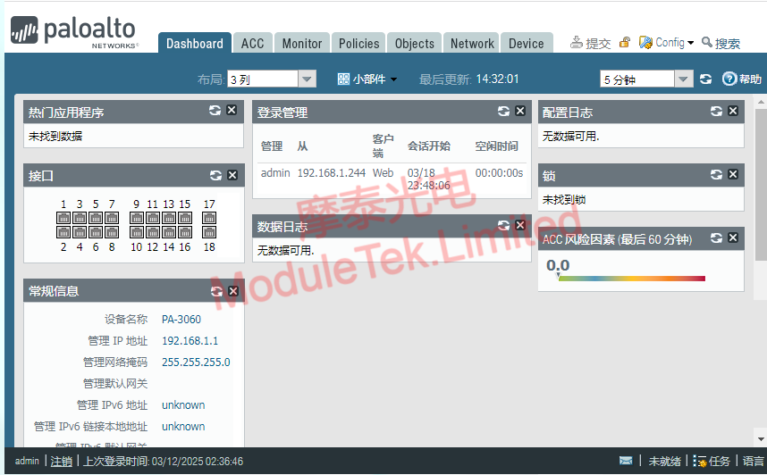
Figure 1 PA-3060 Web Interface Page
2. Go to Objects > Addresses, and click Add to create IP address objects.
You need to create two address objects: the local interface IP of the PA-3060 and the interface IP of the peer switch.

Figure 2 Create IP Address Object
The page after successful creation is displayed as follows.
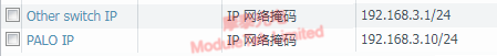
Figure 3 Local and Peer IP Address List
3. Navigate to Network > Zone, click Add to create a new security zone.
Set the zone name and select Layer 3 as the zone type. Click Add under the User ID section, then select the peer IP address created in the previous step.
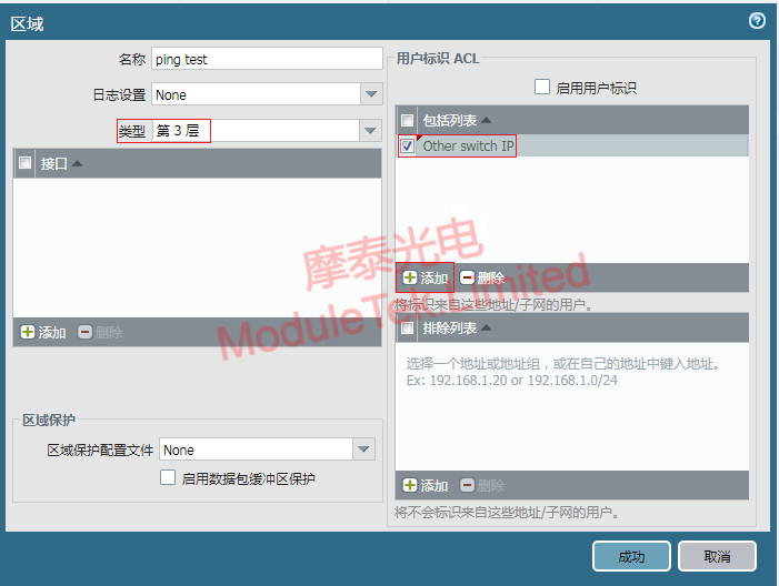
Figure 4 Create and Configure Security Zone
4. Go to Network > Network Profile > Interface Management, click Add to create an interface management profile.
Set the profile name, enable Ping in network services, and add the peer IP address to the Allowed IP Addresses list.
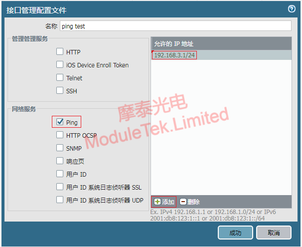
Figure 5 Create and Configure Interface Management Profile
5. Navigate to Network > Interface, select the target interface — Ethernet 1/18 for this test.
Set the interface type to Layer 3 in Ethernet Interface settings; set the virtual router to default, and select the security zone created in Step 3.
In the IPv4 section, click Add and bind the PA-3060 interface IP created in Step 2.
In the Advanced settings, select Management Profile and apply the interface management profile created in Step 4.
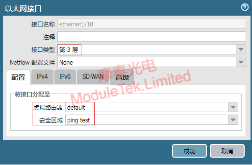
Figure 6 Configure Virtual Router and Security Zone
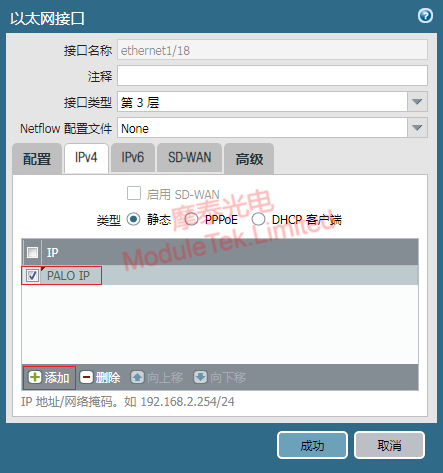
Figure 7 Bind Interface IP Address
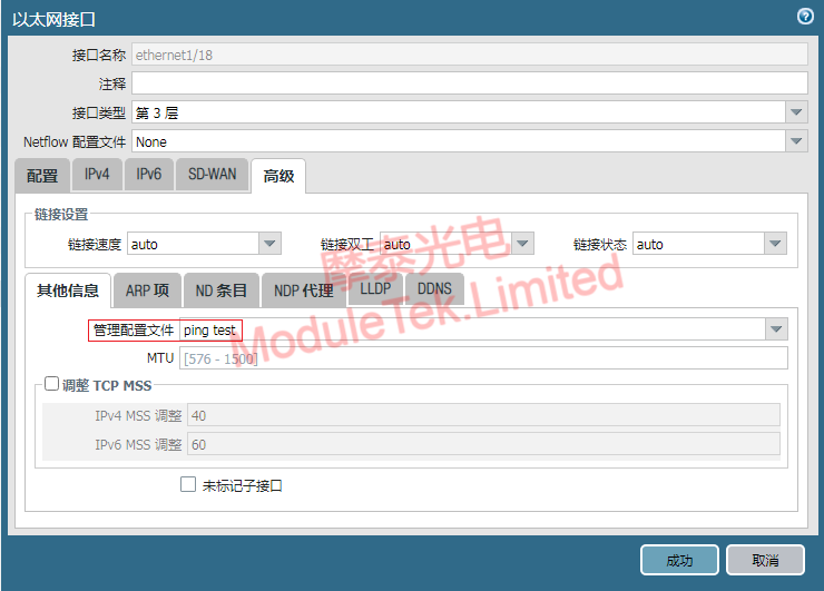
Figure 8 Configure Interface Management Profile
6. Click Submit at the top of the web page to save all configurations.
II. Verify IP Configuration Validity
To confirm whether the configured IP takes effect, use a ping test to check network connectivity.
Use 10G optical modules to connect the PA-3060 with the peer switch (using the preset peer interface IP).
On the firewall web interface, go to Device > Troubleshooting. Select Ping as the test type.
Fill in the PA-3060 interface IP as the source address, and enter the peer switch interface IP in the host address field. Run the test; the ping test will return normal reachability.
The IP configuration steps for the PA-850 are exactly the same as those for the PA-3060.
Moduletek Limited is at your service.
For further inquiries about the above content, please contact us at: sales@moduletek.com


