 40G/100G Optical Transceivers
 25G Optical Transceivers
 10G Optical Transceivers
 155M/2.5G Optical Transceivers
 1G Optical Transceivers
 1G BIDI Optical Transceivers
 Dual-Rate Optical Transceivers
 FC 16G/32G Optical Transceivers
 CWDM Optical Transceivers
 DWDM Optical Transceivers
 SGMII Port Optical Transceivers
 XFP Optical Transceivers
 100M/1G/10G Coppers
 Full-Rate AOC & Breakout Series
 10G/40G Active DAC Series
 Full-Rate Passive DAC Series
 40G/100G Passive Breakout DAC Series
 Regular/MTP-MPO Fiber Patch Cords
 MT2011
 MT2010
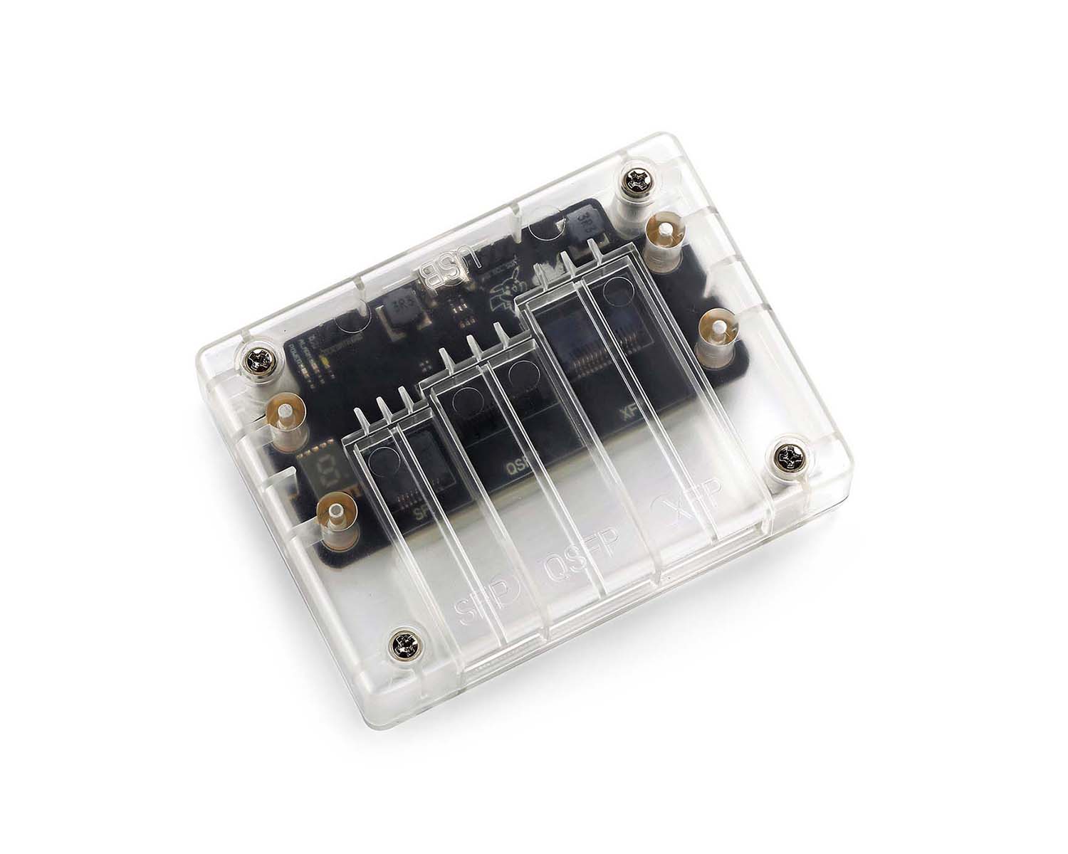 CodingBox
 QSFP to SFP Adapter
MOXA EDS-4014-4GS-2QGS-LV Switch Showcase
Time: 2025-05-15
Moduletek Laboratory has purchased the MOXA EDS-4014-4GS-2QGS-LV industrial switch, which supports testing 1G/2.5G SFP series modules. This article introduces the device unboxing and basic overview.
Table 1 Official Device Specifications
| Model | 10/100BaseT(X) port (RJ45 connector) | 100/100BaseSFP slot | 1000/2500BaseSFP slot | Operating Voltage | Pre-installed power supply module | Operating Temperature |
| EDS-4014-4GS-2QGS-LV | 8 | 4 | 2 | 9.6 to 60VDC | PWR-100-LV | -10 to 60℃ |
1. Product Unboxing
The package contains one switch main unit and technical documents, including the Quick Installation Guide, Warranty Card, Certificate of Conformity, and Product Notice. No additional accessories are included.
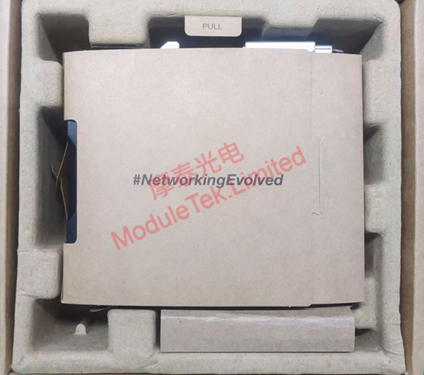
Figure 1 Internal structure of the package
The front panel of the MOXA EDS-4014-4GS-2QGS-LV switch is equipped with 8 × 10/100Base-T ports, 4 × 100/1000Base SFP ports, 2 × 1000/2500Base SFP ports, 1 × RJ45 serial port, 1 × reserved USB port, and 2 × DC power supply connectors.
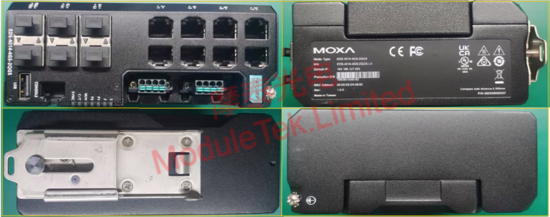
Figure 2 Device Panel
Open the side dust cover, and you will see an SD card slot, a reset button and a DIP switch inside.
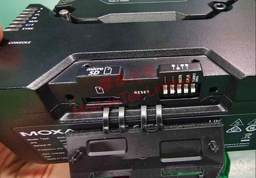
Figure 3 Device SD card slot
The switch adopts a compact enclosure design, suitable for deployment in narrow spaces. All interface labels and LED indicators are arranged on two panels, making it convenient to check the device operating status from different angles.
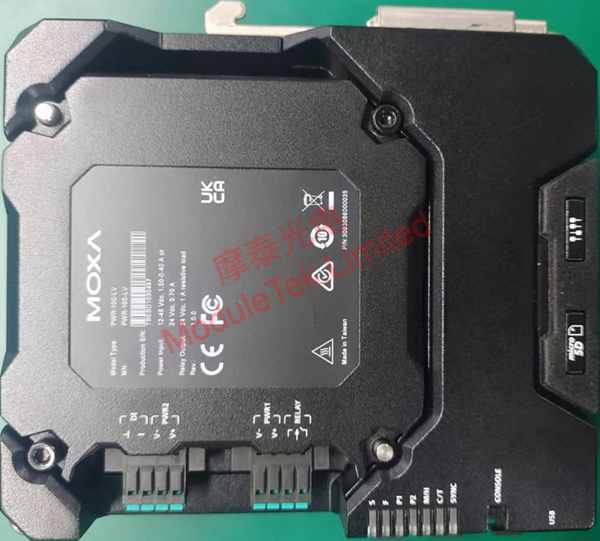
Figure 4 Device bottom panel
2. Device Management
The device supports management via Command Line Interface (CLI) and Web Graphical User Interface (GUI).
Connect the power cord to power on the device. Use a MOXA RJ45-to-DB9 serial cable to connect your computer to the switch serial port.
Default baud rate: 115200
Default username/password: admin/moxa
You can then log in to the device console.
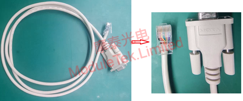
Figure 5 MOXA serial cable
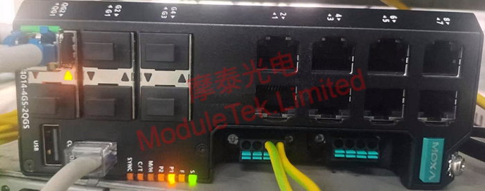
Figure 6 Device power-up
Use Moduletek SFP-GE-LX compatible modules and patch cords to connect to the MOXA EDS-4014-4GS-2QGS-LV switch. The module can establish a normal link.
Execute the following command to check interface status and module identification information:
show interfaces <interface-type> <interface-id>
Connect your PC to any RJ45 port of the switch. The default management IP is 192.168.127.253. Open a local browser to access the web management page, where the homepage displays device and system information.
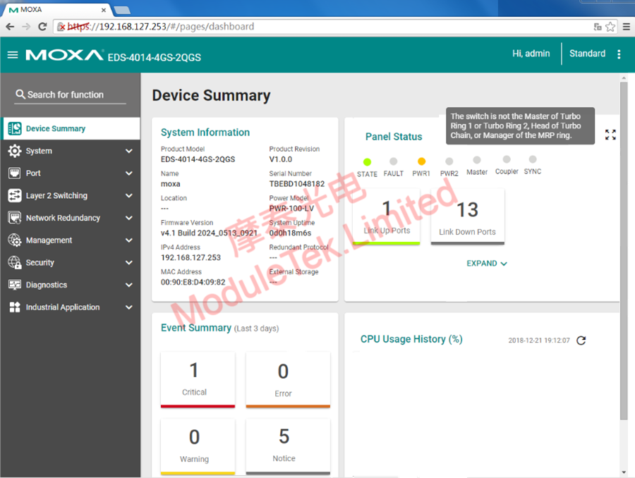
Figure 7 WEB interface home page
You can view interface status by navigating to Device Summary > Panel Status > EXPAND on the web page.
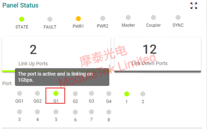
Figure 8 Interface Status Information
Go to Port > Port Interface > Port Settings to check the interface module type. The page does not display optical module DOM information.
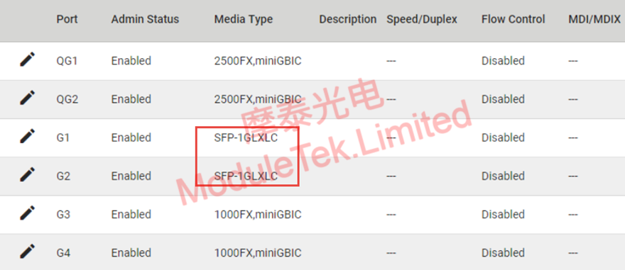
Figure 9 Interface Identification Type
Moduletek optical modules feature good compatibility with MOXA devices. Welcome to inquire and purchase.
For further inquiries about the above content, please contact us at: sales@moduletek.com


