 40G/100G Optical Transceivers
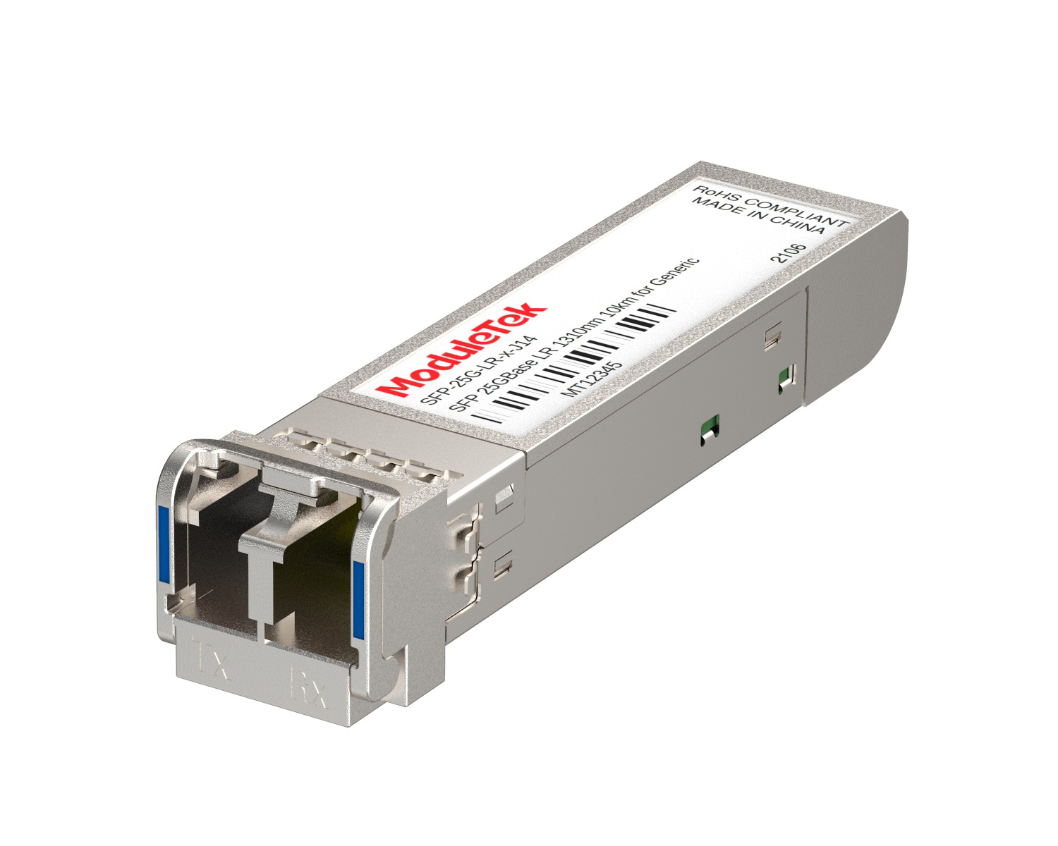 25G Optical Transceivers
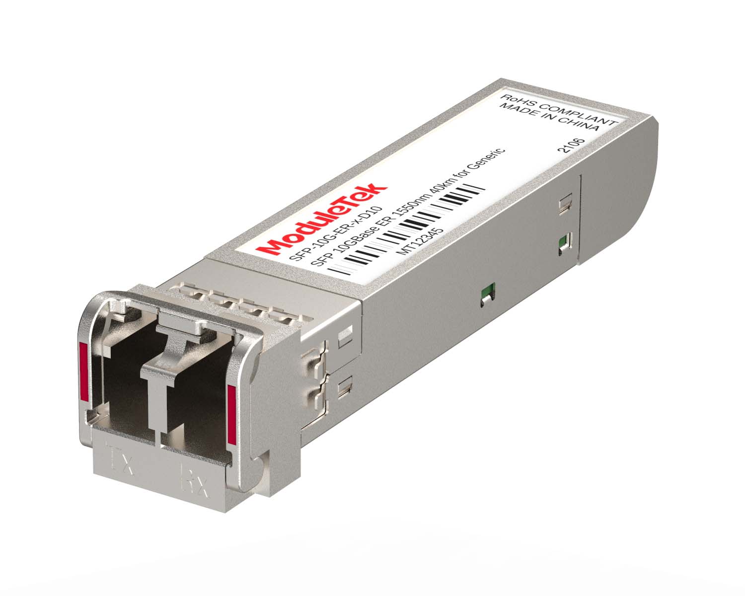 10G Optical Transceivers
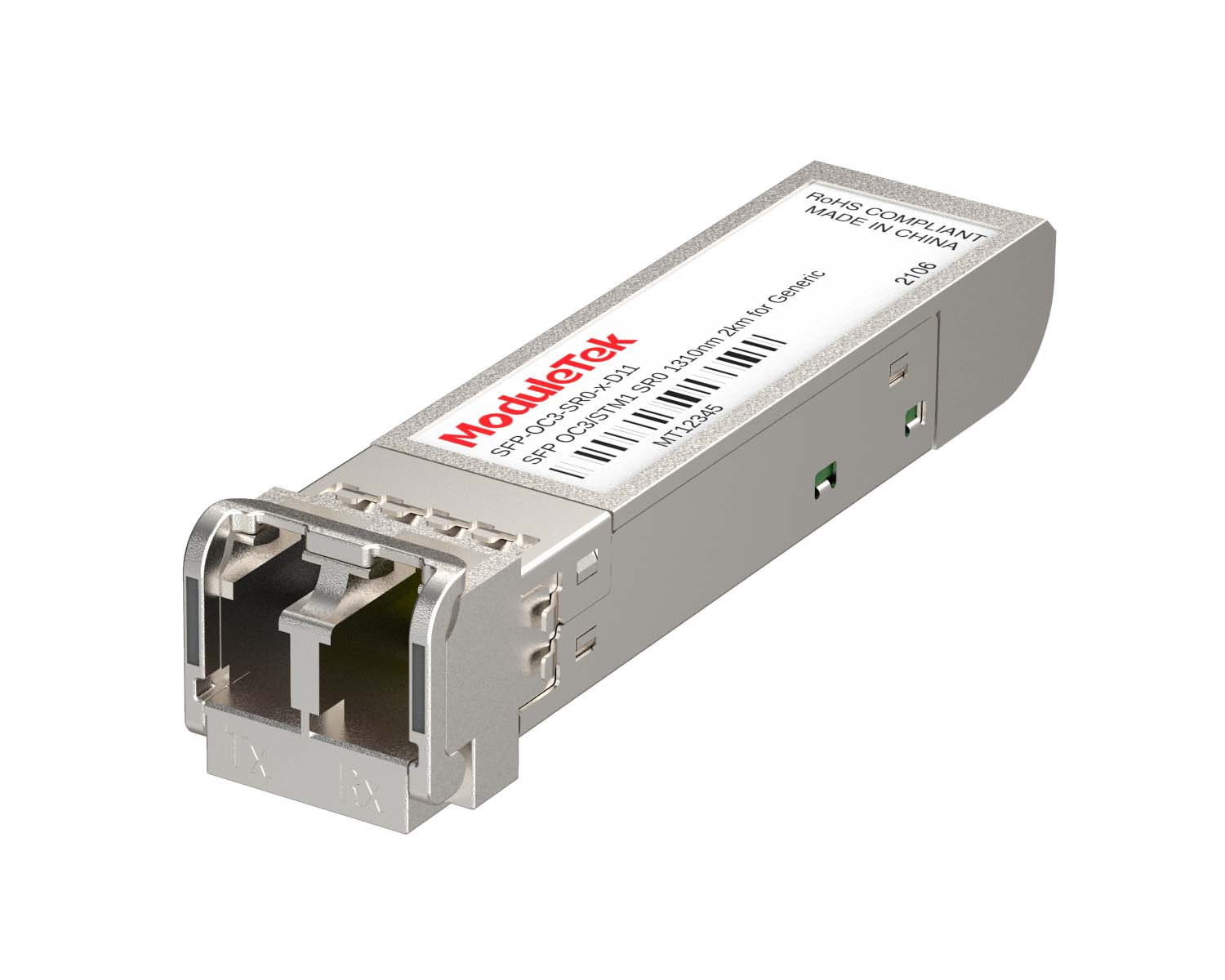 155M/2.5G Optical Transceivers
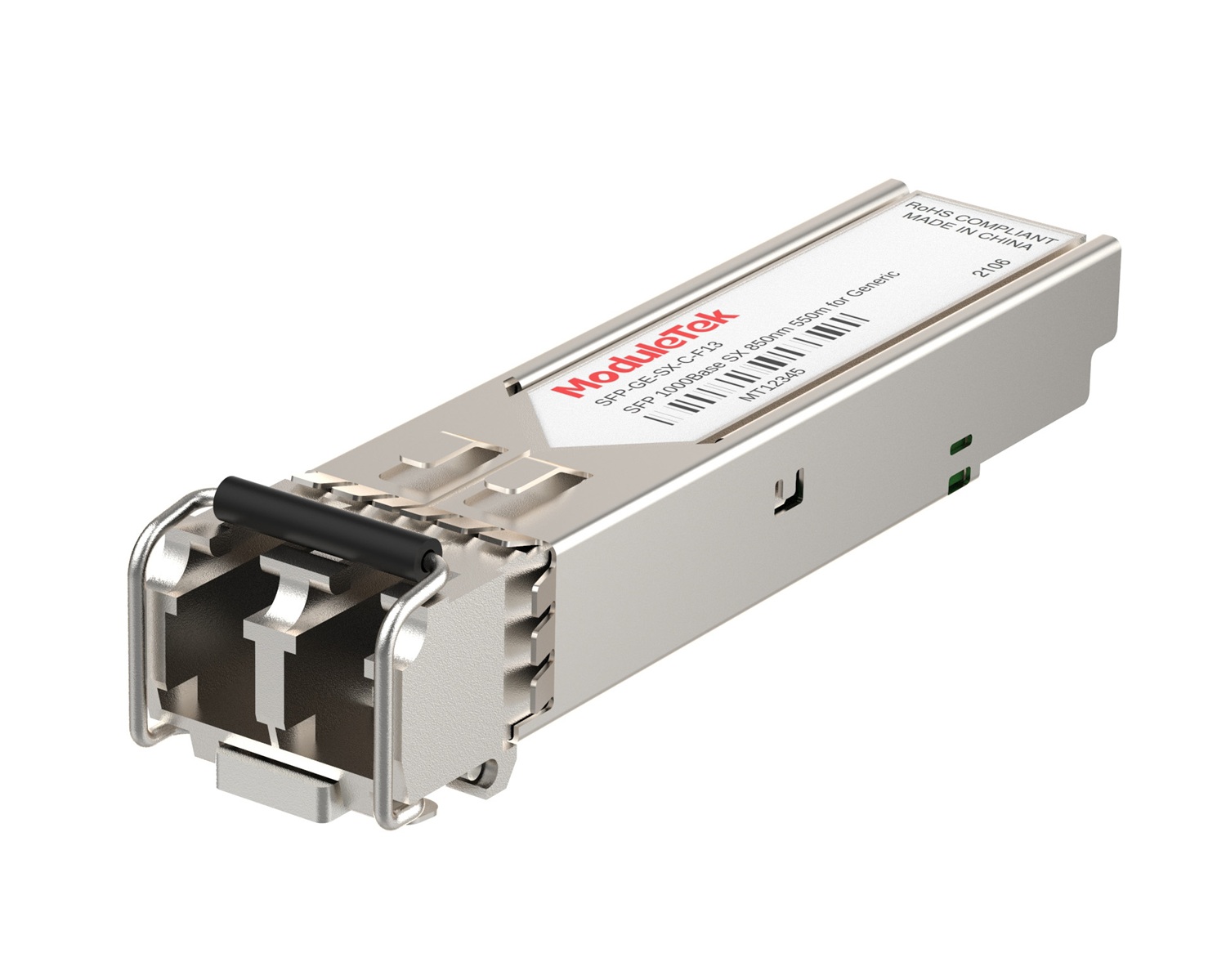 1G Optical Transceivers
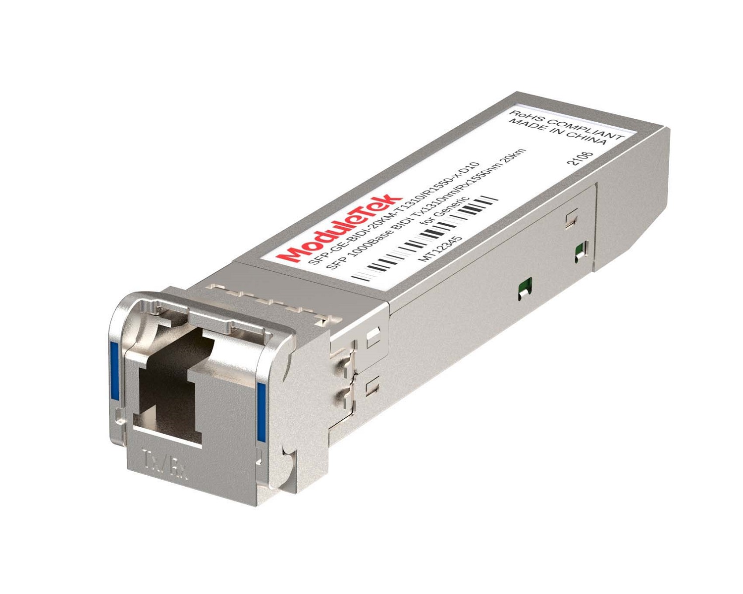 1G BIDI Optical Transceivers
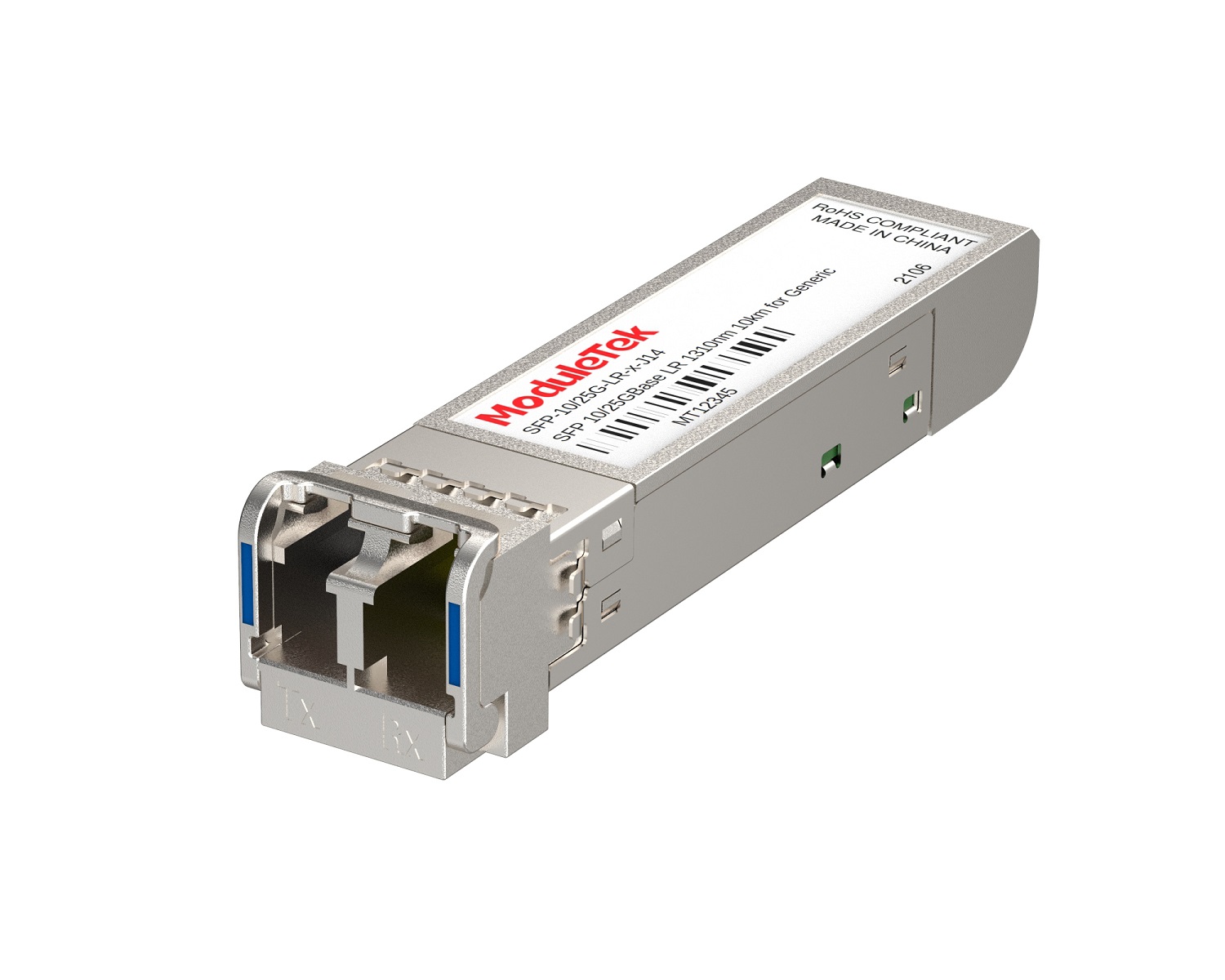 Dual-Rate Optical Transceivers
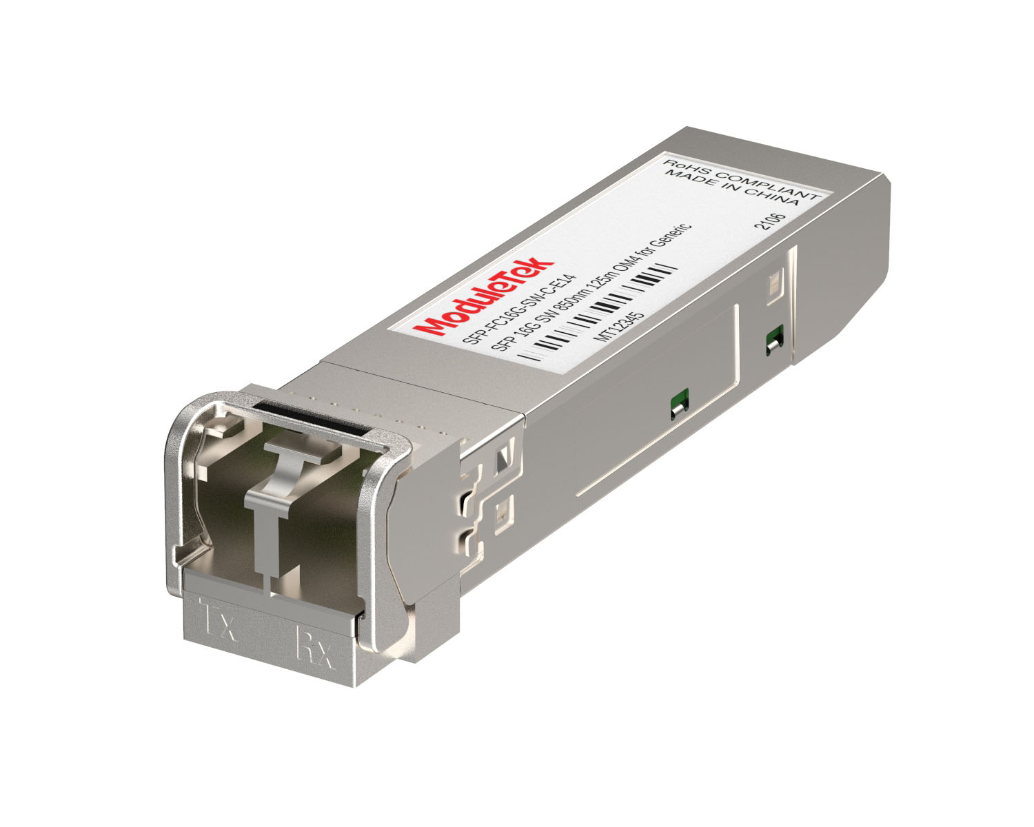 FC 16G/32G Optical Transceivers
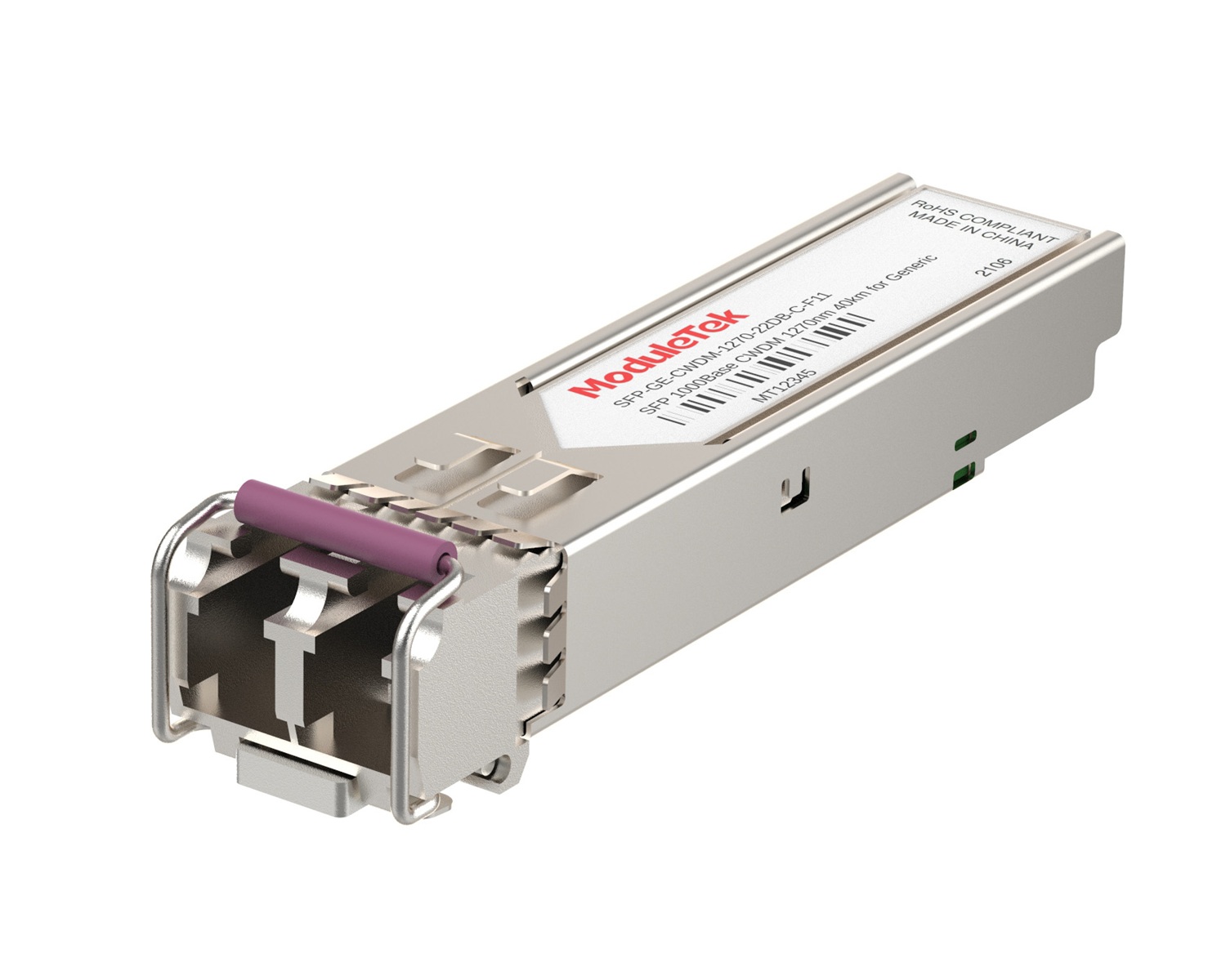 CWDM Optical Transceivers
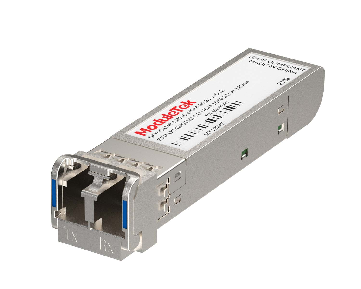 DWDM Optical Transceivers
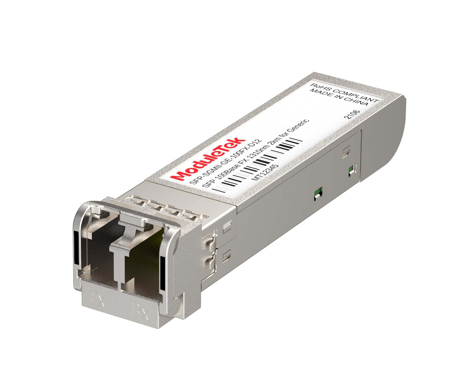 SGMII Port Optical Transceivers
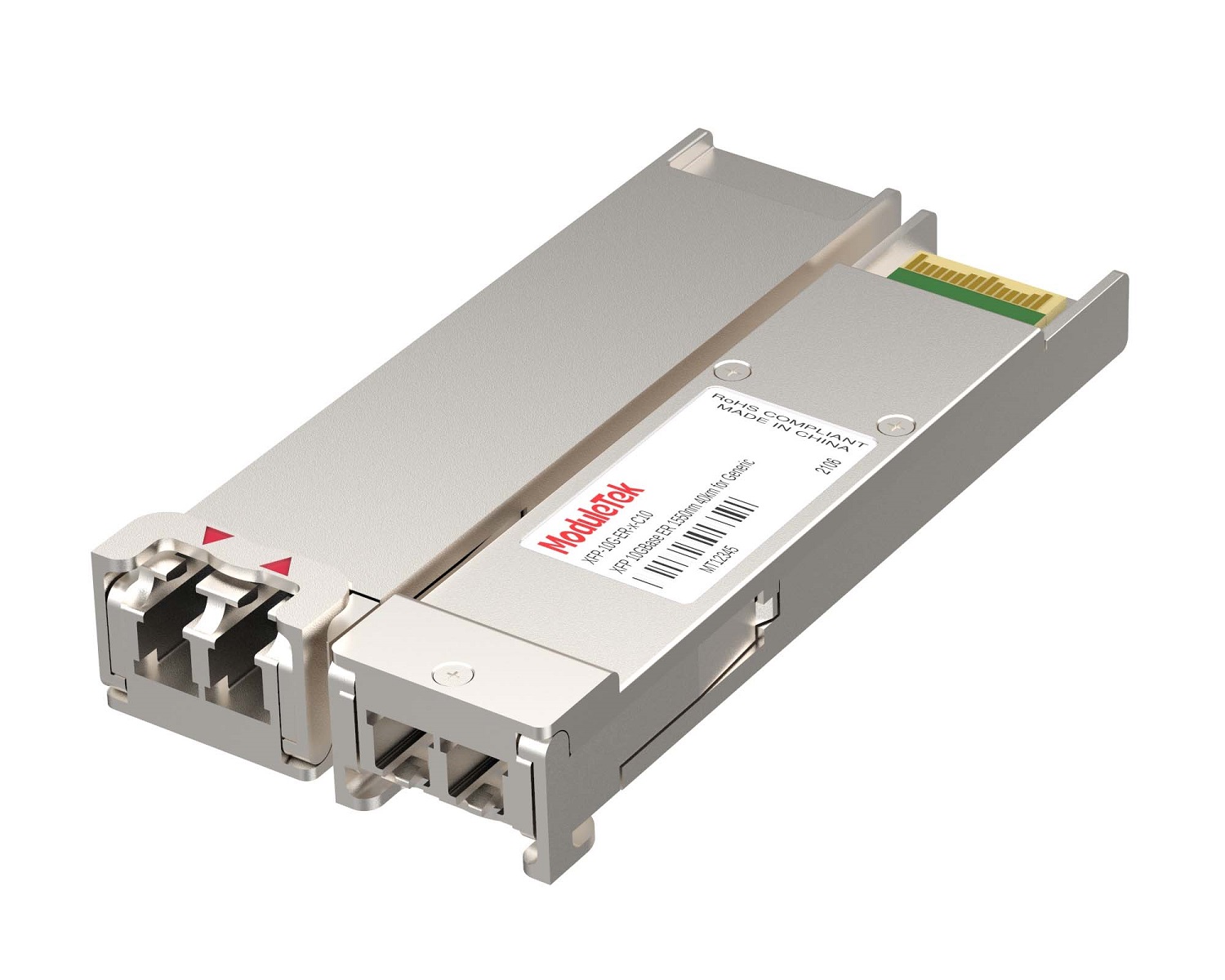 XFP Optical Transceivers
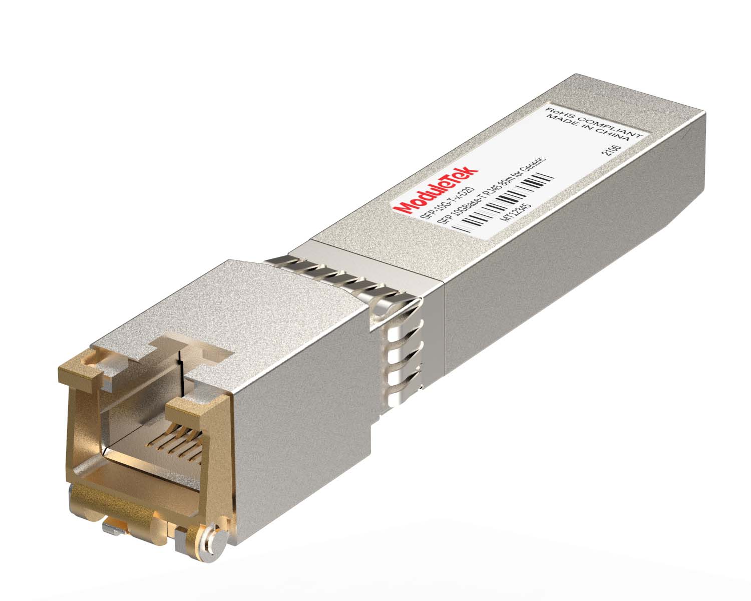 100M/1G/10G Coppers
 Full-Rate AOC & Breakout Series
 10G/40G Active DAC Series
 Full-Rate Passive DAC Series
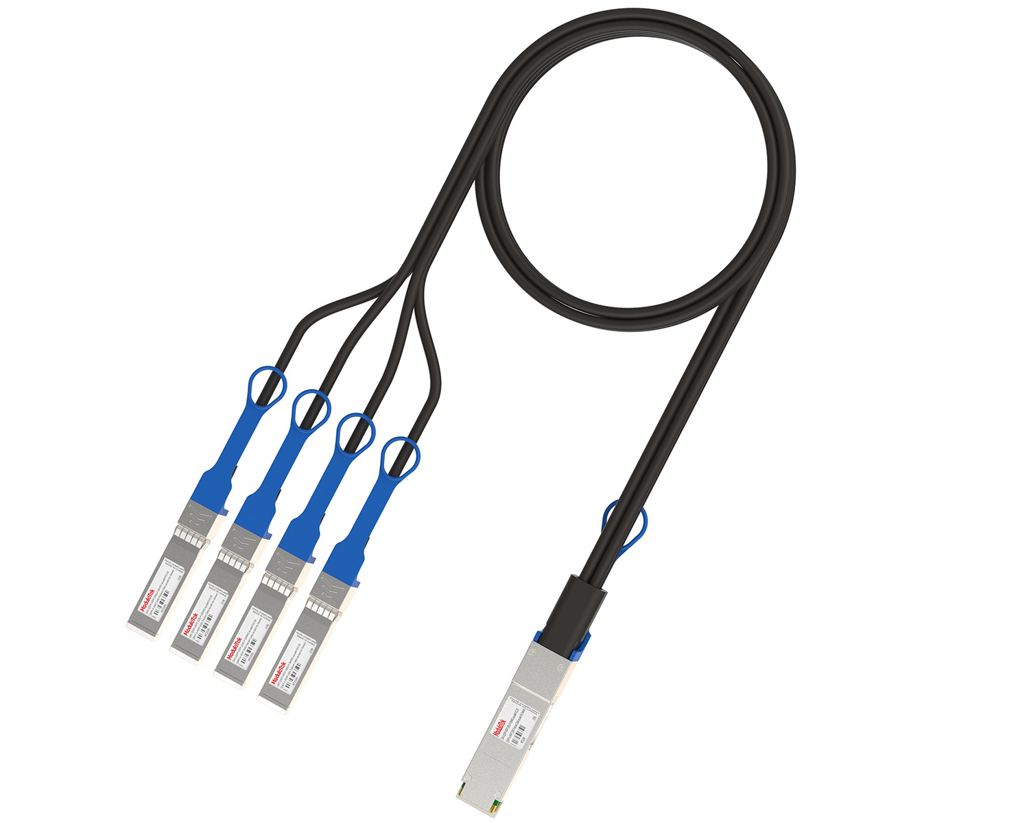 40G/100G Passive Breakout DAC Series
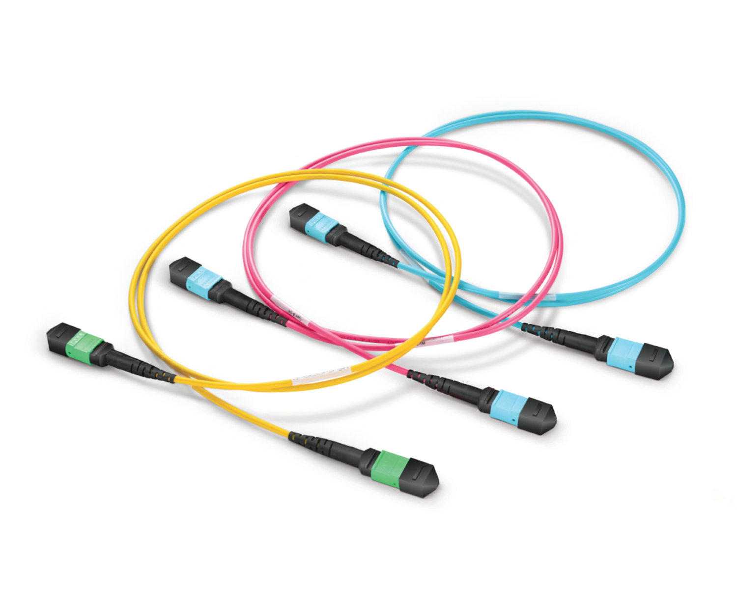 Regular/MTP-MPO Fiber Patch Cords
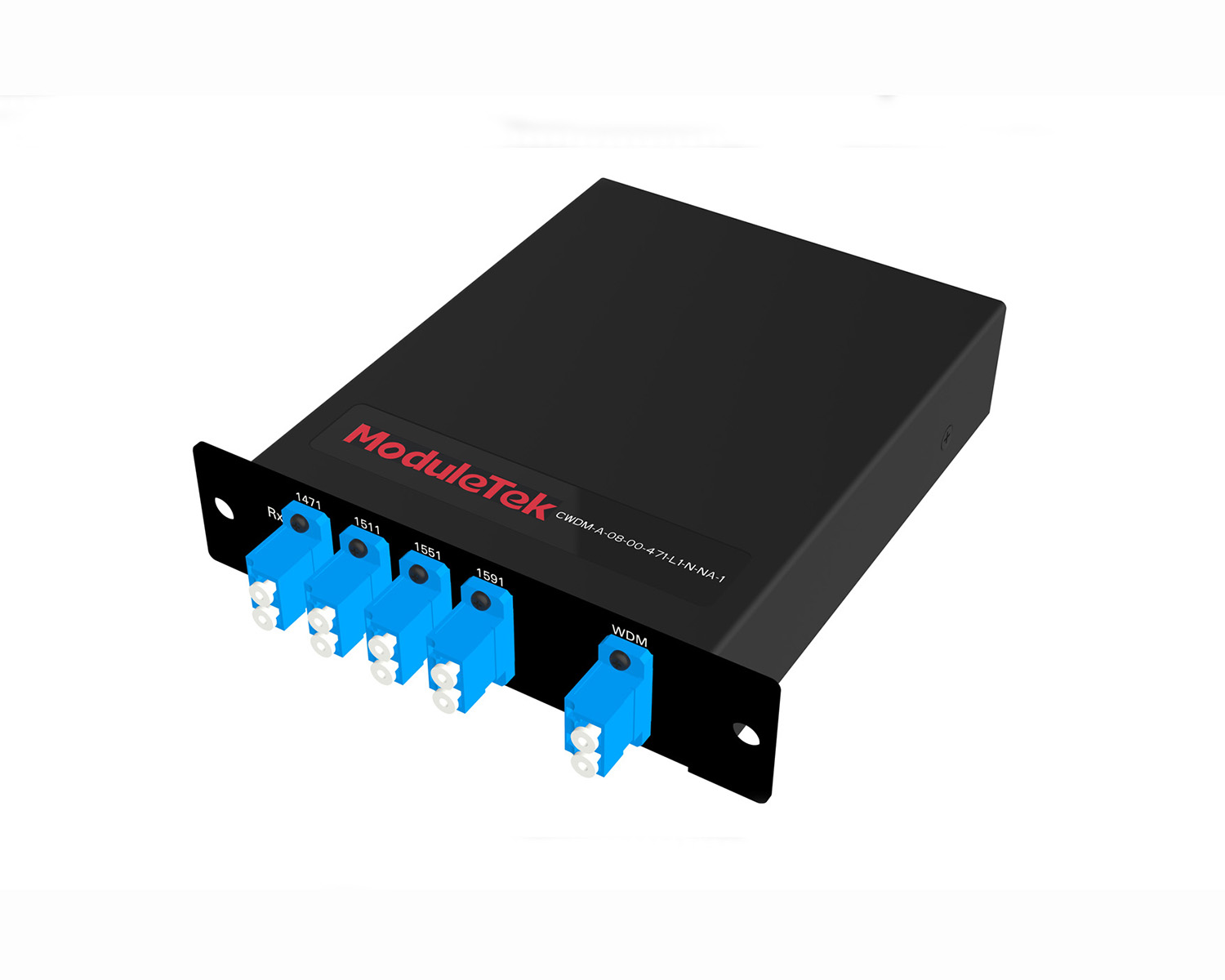 MT2011
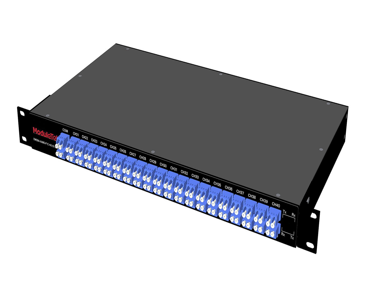 MT2010
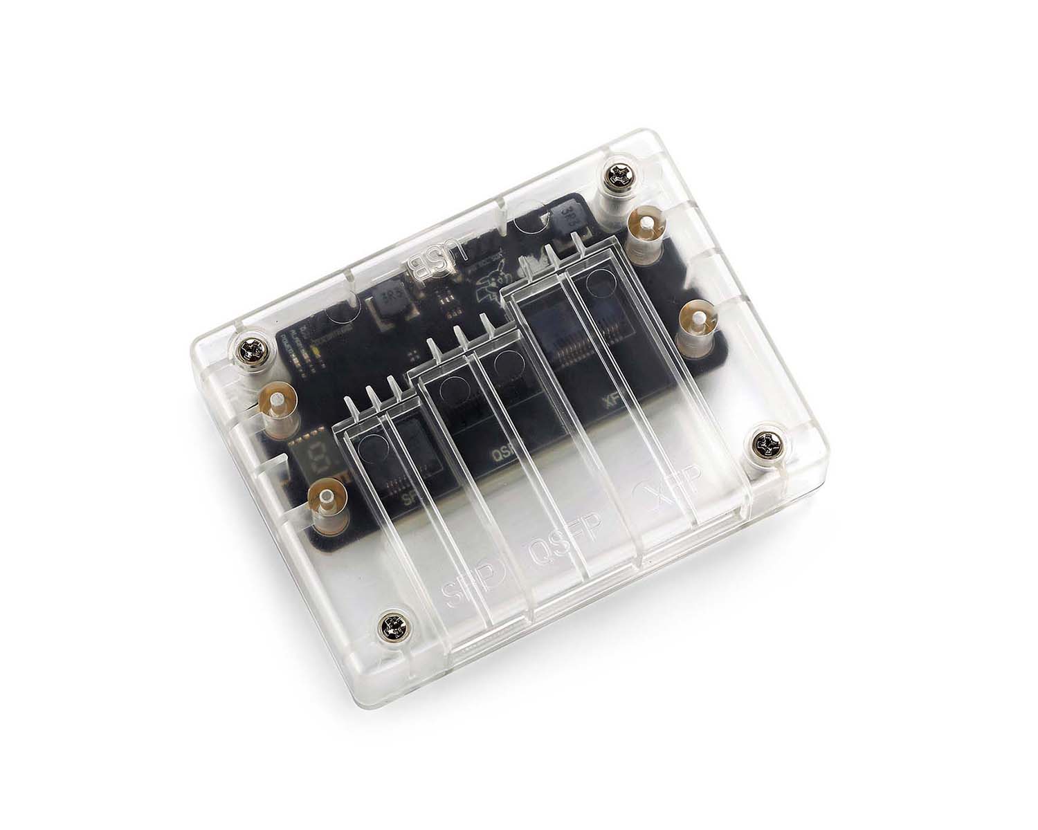 CodingBox
 QSFP to SFP Adapter
Digital Diagnostic Monitoring (DDM) Function Of Optical Modules
Time: 2020-02-24
1. Digital Diagnostic Monitoring Function
DDM, short for Digital Diagnostic Monitoring, literally refers to the function of diagnosing the working status of optical modules, functioning like a diagnostic tool. It can provide the host with real-time data about the module’s internal operating conditions, including parameters such as voltage, temperature, transmit optical power, receive optical power, and bias current. Devices can use this function to read and display the real-time operating parameters of the optical module. Figure 1 shows the DDM test data of our SFP-10G-LR module on a Cisco 9500 switch.
Real-time operating status data of Motai SFP-10G-LR on Cisco 9500 switch:
2. Applications of the DDM Function
2.1 Real-time Monitoring of Module Operating Status
The primary function of DDM is to verify whether the module’s working environment and its own operating parameters are within normal ranges. Only under standard-compliant environmental conditions can the optical module maintain nominal performance. In some cases, when environmental parameters exceed the limits specified in the datasheet or relevant standards, the module’s performance may degrade, leading to transmission bit errors.
Common scenarios of incompatibility between the working environment and the module include:
• Voltage exceeding the specified range
• Receive optical power being either overloaded or lower than the receiver sensitivity
• Temperature going beyond the operating temperature range
Deterioration of the module’s own performance may also cause abnormalities such as decreased transmit optical power and excessive bias current.
2.2 Fault Localization
In optical links, quickly identifying the location of a fault is crucial for service continuity. Network administrators can leverage DDM data to troubleshoot common network faults, such as link interruptions caused by lack of received optical signals.
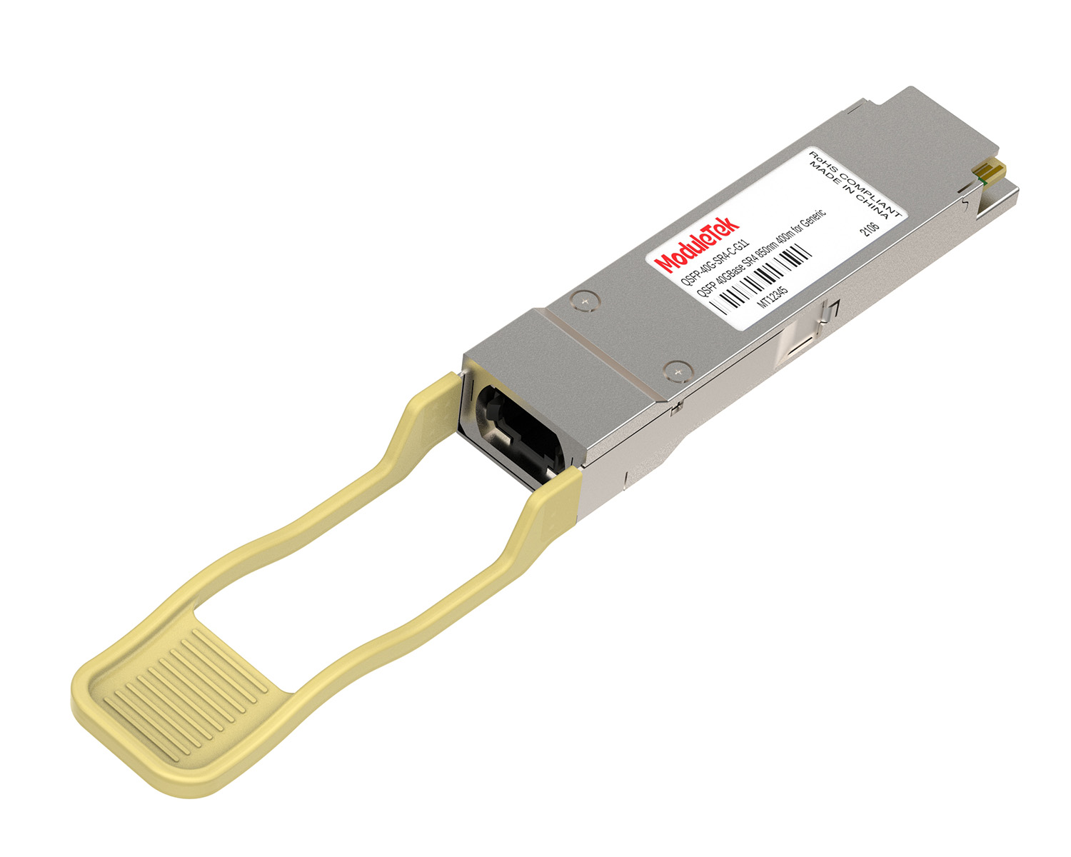
All optical modules manufactured by Moduletek are equipped with the DDM function, and the reporting accuracy complies with international specifications. Figure 2 shows the physical image of our optical module.
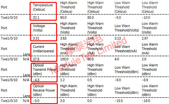
Figure 1 Physical Image of Moduletek Optical Module
For further inquiries about the above content, please contact us at: sales@moduletek.com


