 40G/100G Optical Transceivers
 25G Optical Transceivers
 10G Optical Transceivers
 155M/2.5G Optical Transceivers
 1G Optical Transceivers
 1G BIDI Optical Transceivers
 Dual-Rate Optical Transceivers
 FC 16G/32G Optical Transceivers
 CWDM Optical Transceivers
 DWDM Optical Transceivers
 SGMII Port Optical Transceivers
 XFP Optical Transceivers
 100M/1G/10G Coppers
 Full-Rate AOC & Breakout Series
 10G/40G Active DAC Series
 Full-Rate Passive DAC Series
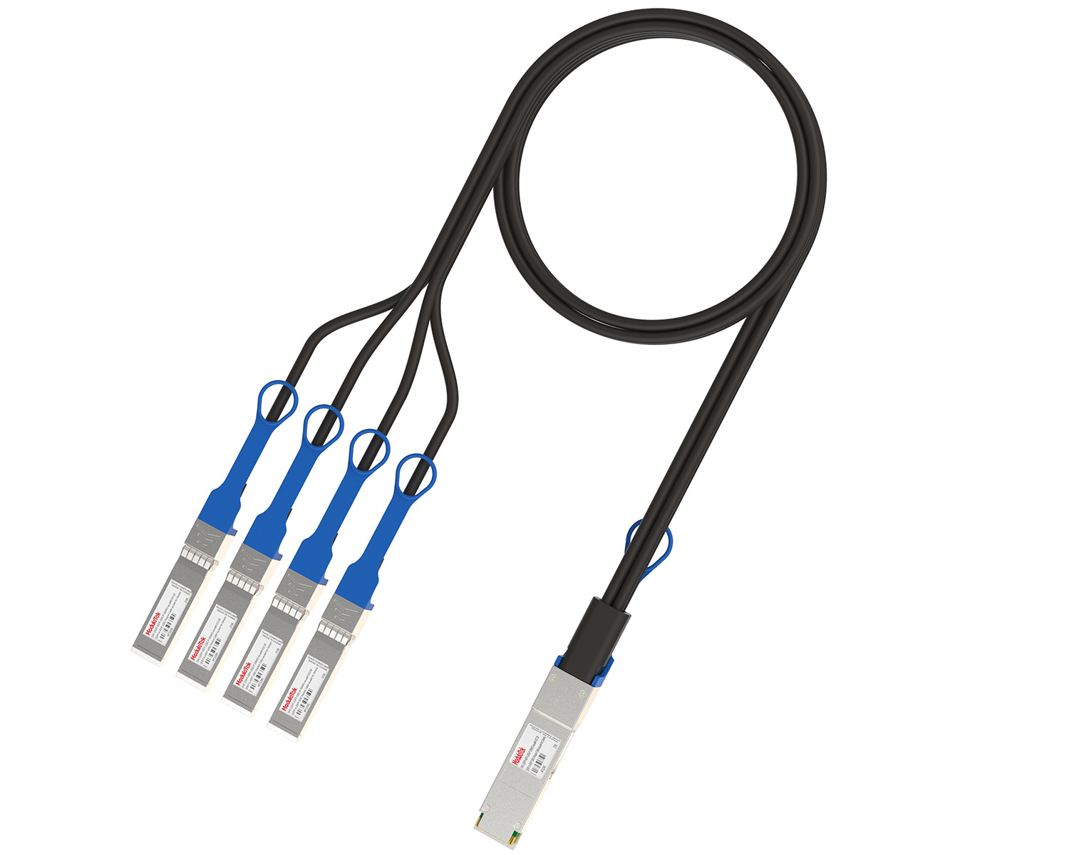 40G/100G Passive Breakout DAC Series
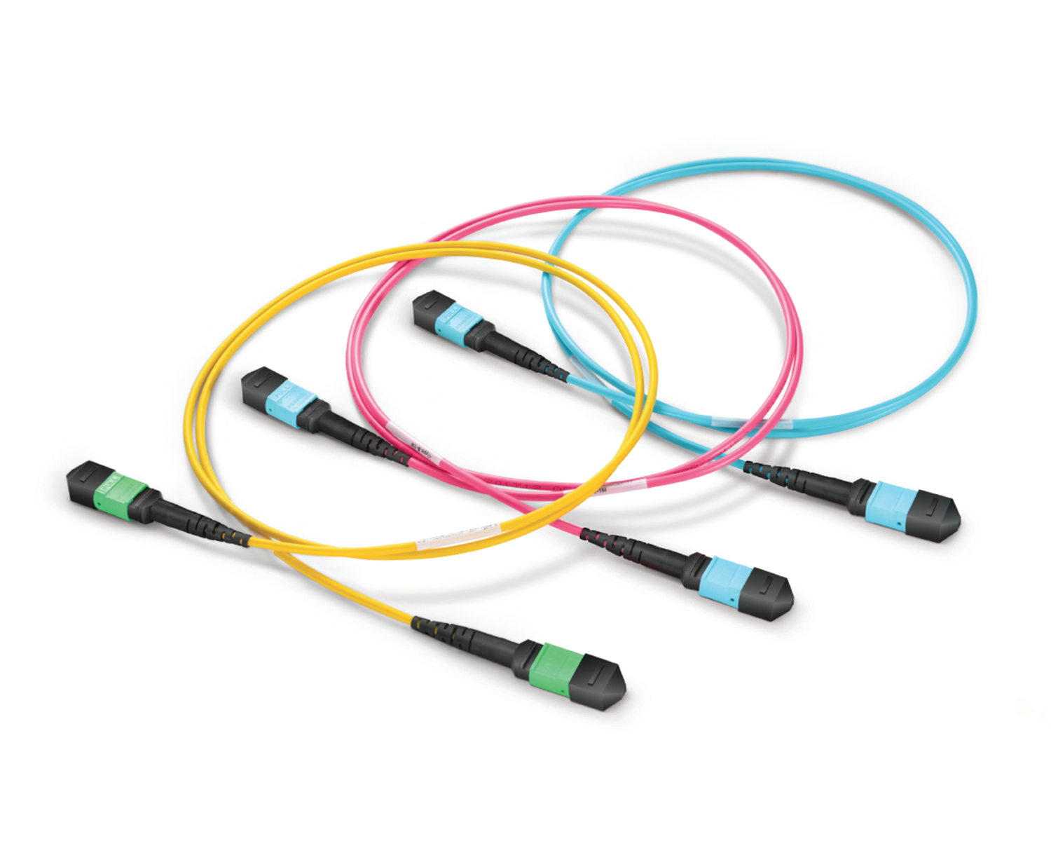 Regular/MTP-MPO Fiber Patch Cords
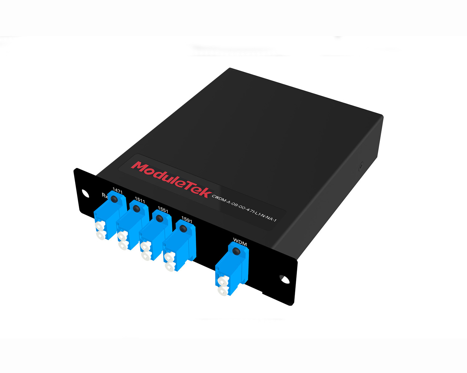 MT2011
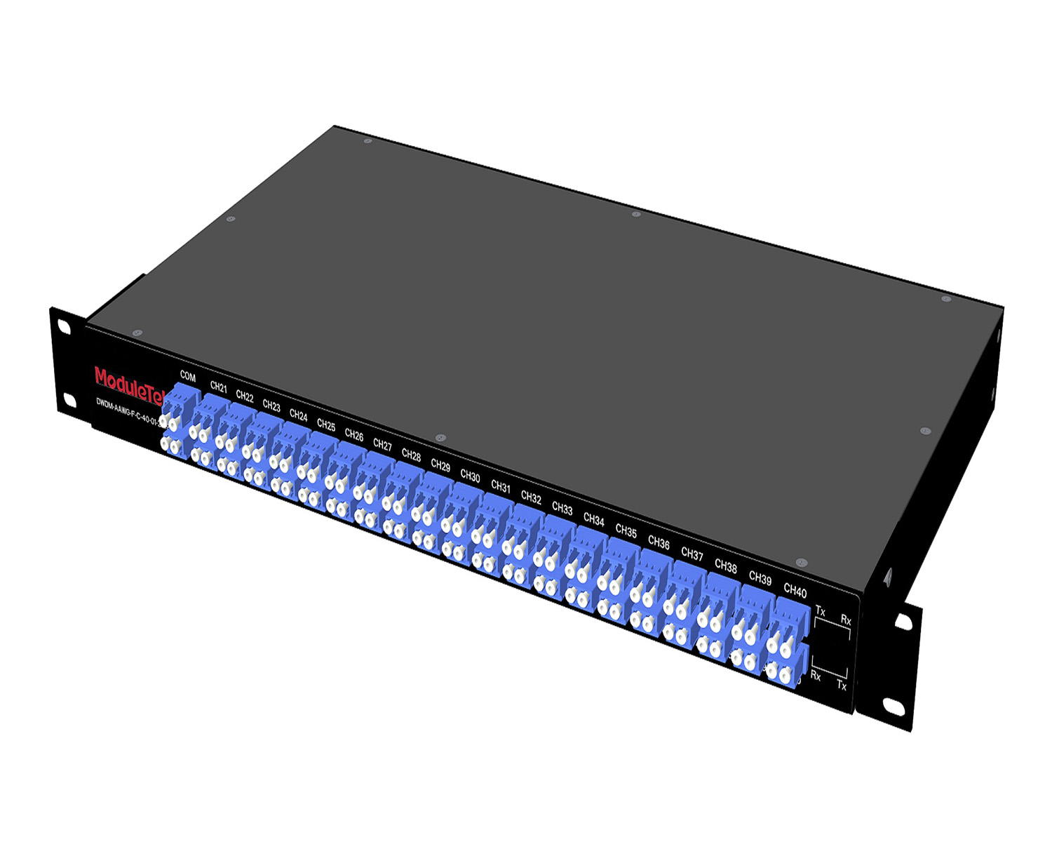 MT2010
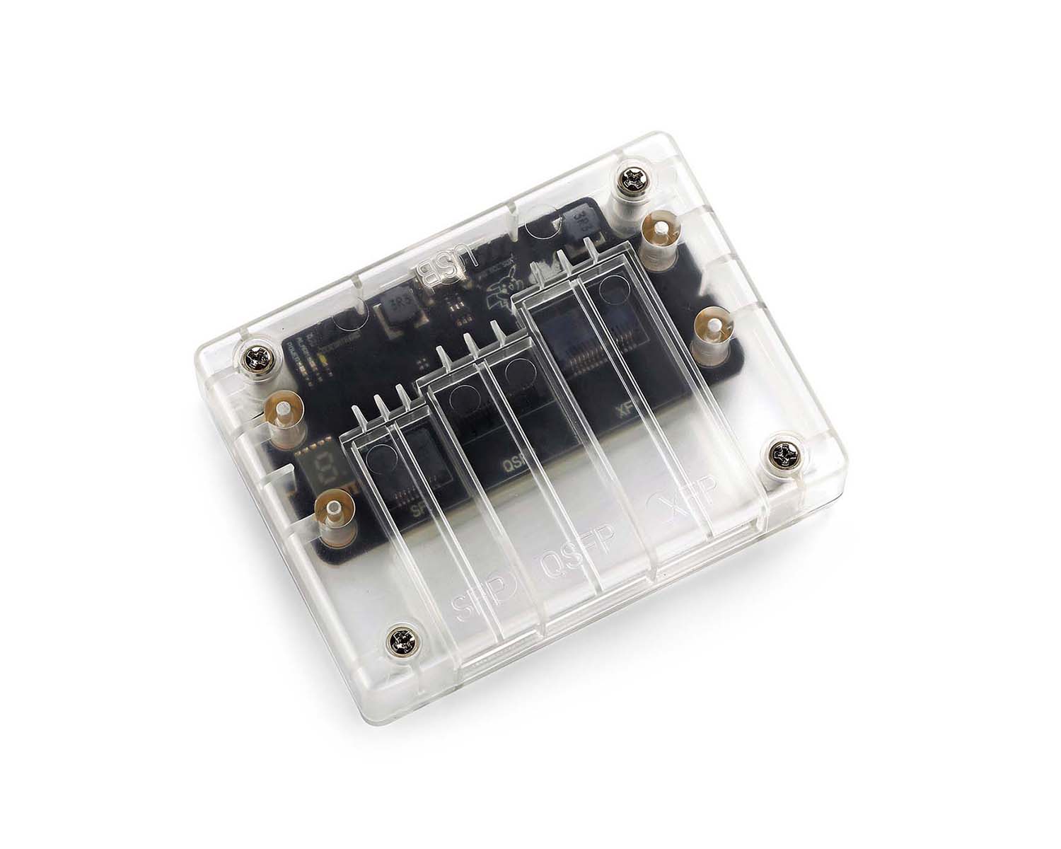 CodingBox
 QSFP to SFP Adapter
CWDM Wavelength Division Multiplexer
Time: 2020-03-29
WDM (Wavelength Division Multiplexing) includes CWDM (Coarse Wavelength Division Multiplexing) and DWDM (Dense Wavelength Division Multiplexing). Both are passive wavelength division multiplexers that operate without a power supply. Combining WDM with WDM modules can form a low-cost transmission solution for the MAN (Metropolitan Area Network) access layer, which fully utilizes the bandwidth capacity of a single optical fiber and thus reduces the cost of optical fiber utilization.
1. Working Principle of WDM
Simply put, at the transmitting end, WDM combines signals of different wavelengths (carrying the information to be transmitted) through a multiplexer (also called a wavecombiner) and couples them into the same optical fiber for transmission over the optical line. At the receiving end, a demultiplexer (also called a wavesplitter) separates the optical carriers of different wavelengths, which are then further processed by an optical module to restore the original signal. Both CWDM and DWDM follow this principle, with the key difference being the wavelength interval: CWDM has a larger interval of 20nm, while DWDM has a very small interval of 0.8nm or 0.4nm.
Multiplexing refers to the co-transmission of optical signals of different wavelengths over the same fiber. The advantage of this is saving transmission fibers. Although the cost of the fiber itself is not high, the cost of fiber laying and construction is substantial. Therefore, reducing the number of fiber channels for transmission can significantly save costs.
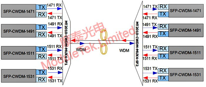
Figure 1 Dual-Fiber Bidirectional WDM
2. WDM Form Factors
There are two common WDM form factors: a small LGX chassis and a 19-inch 1U rackmount chassis, as shown in the following figures:
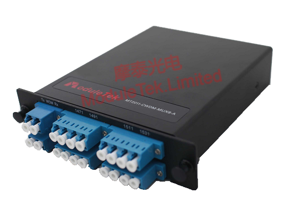
Figure 2 LGX Chassis
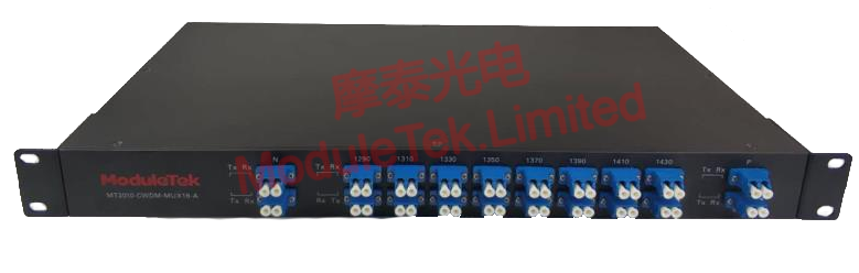
Figure 3 19-Inch 1U Rackmount Chassis
Chassis of different sizes have different channel capacities. Generally, WDM with fewer than 8 channels can use either chassis, while those with more than 8 channels can only use the 1U rackmount chassis.
3. Internal Structure of WDM
Removing the outer frame of a WDM reveals an ABS plastic box (as shown below), from which several optical fibers and connectors extend.
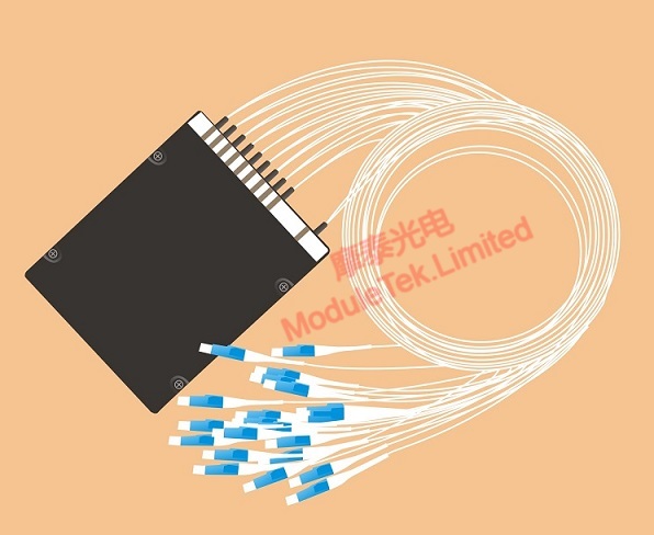
Figure 4 Internal Structure of Wavelength Division Multiplexer
Further disassembling the ABS box exposes its internal structure (as shown below), which contains several glass tubes corresponding to different wavelengths, with optical fibers extending from both ends of each glass tube. These glass tubes are the core components of WDM, responsible for converging and separating signals of different wavelengths.
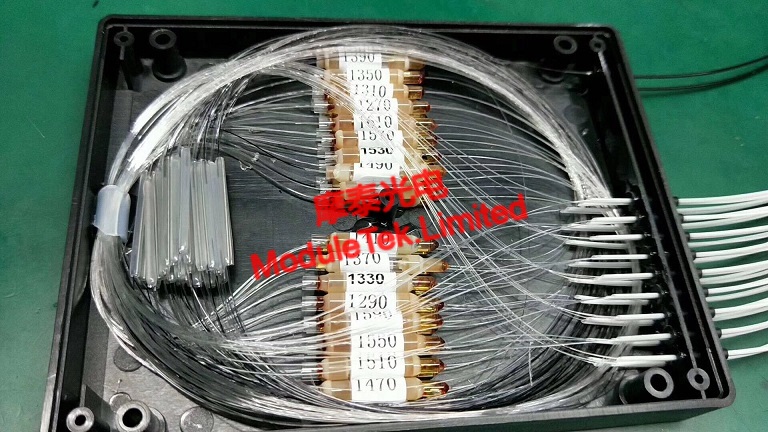
Figure 5 Internal Structure of ABS Box
4. Differences Between CWDM and DWDM
CWDM and DWDM share similar working principles and structures but have the following differences:
• Wavelength Range & Channel Count: CWDM operates in the wavelength range of 1270nm to 1610nm with a 20nm interval, supporting a maximum of 18 channels. A typical DWDM supports a maximum of 40 channels.
• Cost: The coating process of the filter (the core component of DWDM) is much more complex and difficult than that of CWDM. Thus, DWDM is more expensive than CWDM.
5. Special Ports of WDM
In addition to conventional transmission service ports, WDM can be equipped with three types of special ports: pass-through port, monitor port, and 1310 port (Grey Port).
• Pass-Through Port (Express Port): Used for further service expansion. For example, if only 4 channels of service capacity are needed currently but future demand is expected to grow, a WDM with a pass-through port can be selected. This allows direct connection of a new WDM to the pass-through port when expanding services, without replacing or disassembling the existing system. As shown in the unidirectional example below, the original WDM (1471/1491/1511/1531nm) is equipped with a pass-through port; when expanding services, a new WDM (1551/1571/1591/1611nm) is connected to the pass-through port to enable 4 additional channels of service.
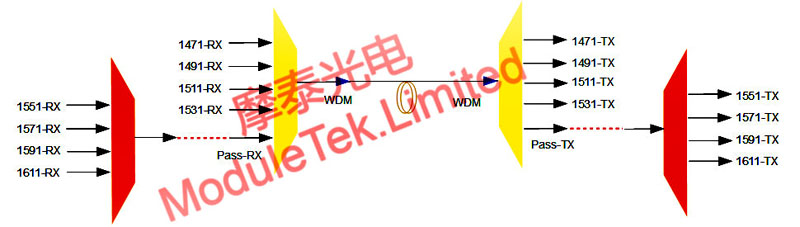
Figure 6 Pass-Through Ports
• Monitor Port: Used to monitor the optical power of public service ports. As shown below, the optical power ratio between the monitor port and the main line service port is 1:99. A significant decrease in the optical power of the monitor port indicates a fault in the main line, requiring timely countermeasures.
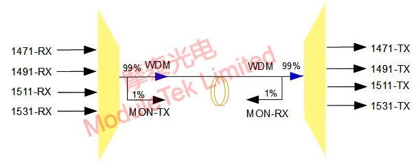
Figure 7 Monitor Port
• 1310 Port (Grey Port): Different from the 1311nm port used for service transmission. The Grey Port has a bandwidth of ±40nm, while the 1311nm service port has a bandwidth of ±6.5nm. It can be used for signal transmission of conventional 1310nm 1G/10G/40G/100G rate grey optical modules.
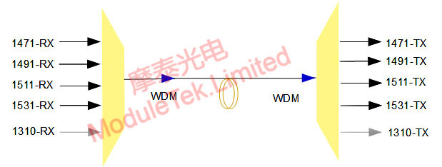
Figure 8 Grey Port
6. Summary
This article briefly introduces the basic concepts of WDM to help customers gain a preliminary understanding. For in-depth insights into solving practical application problems, follow-up introductions will be provided.
Moduletek provides the products mentioned in this application guide. Welcome to place your orders!
For further inquiries about the above content, please contact us at: sales@moduletek.com


