 40G/100G Optical Transceivers
 25G Optical Transceivers
 10G Optical Transceivers
 155M/2.5G Optical Transceivers
 1G Optical Transceivers
 1G BIDI Optical Transceivers
 Dual-Rate Optical Transceivers
 FC 16G/32G Optical Transceivers
 CWDM Optical Transceivers
 DWDM Optical Transceivers
 SGMII Port Optical Transceivers
 XFP Optical Transceivers
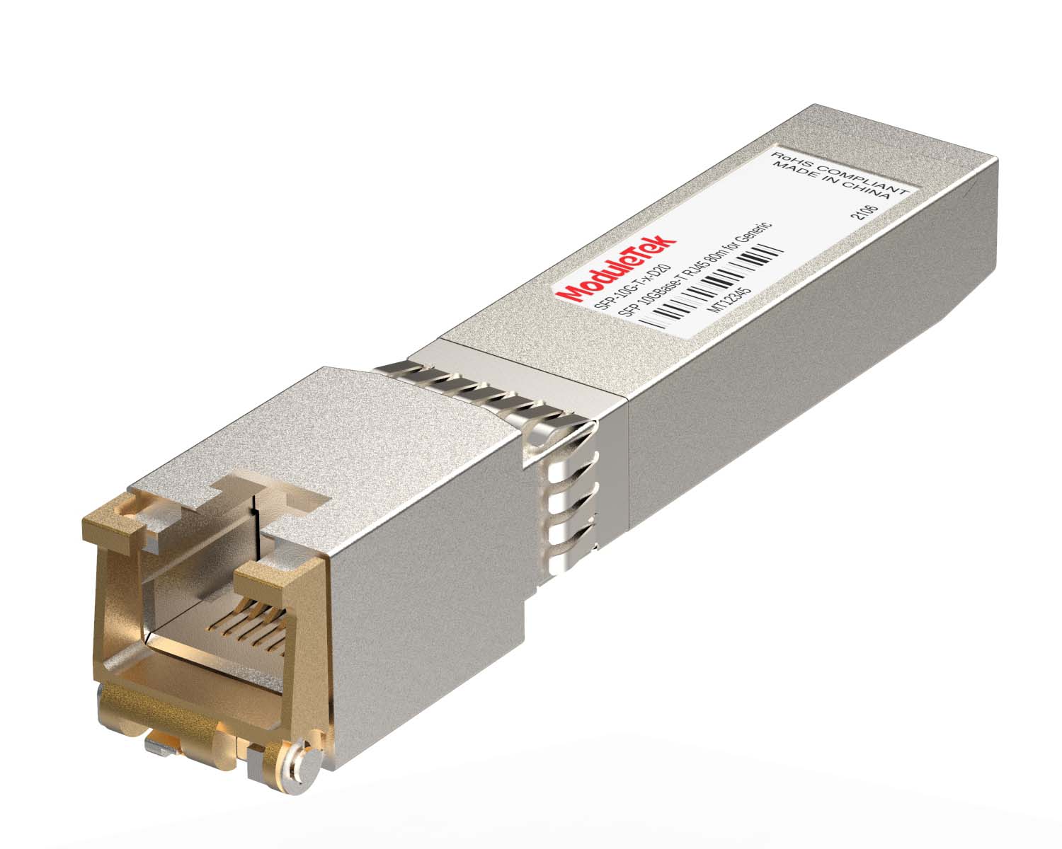 100M/1G/10G Coppers
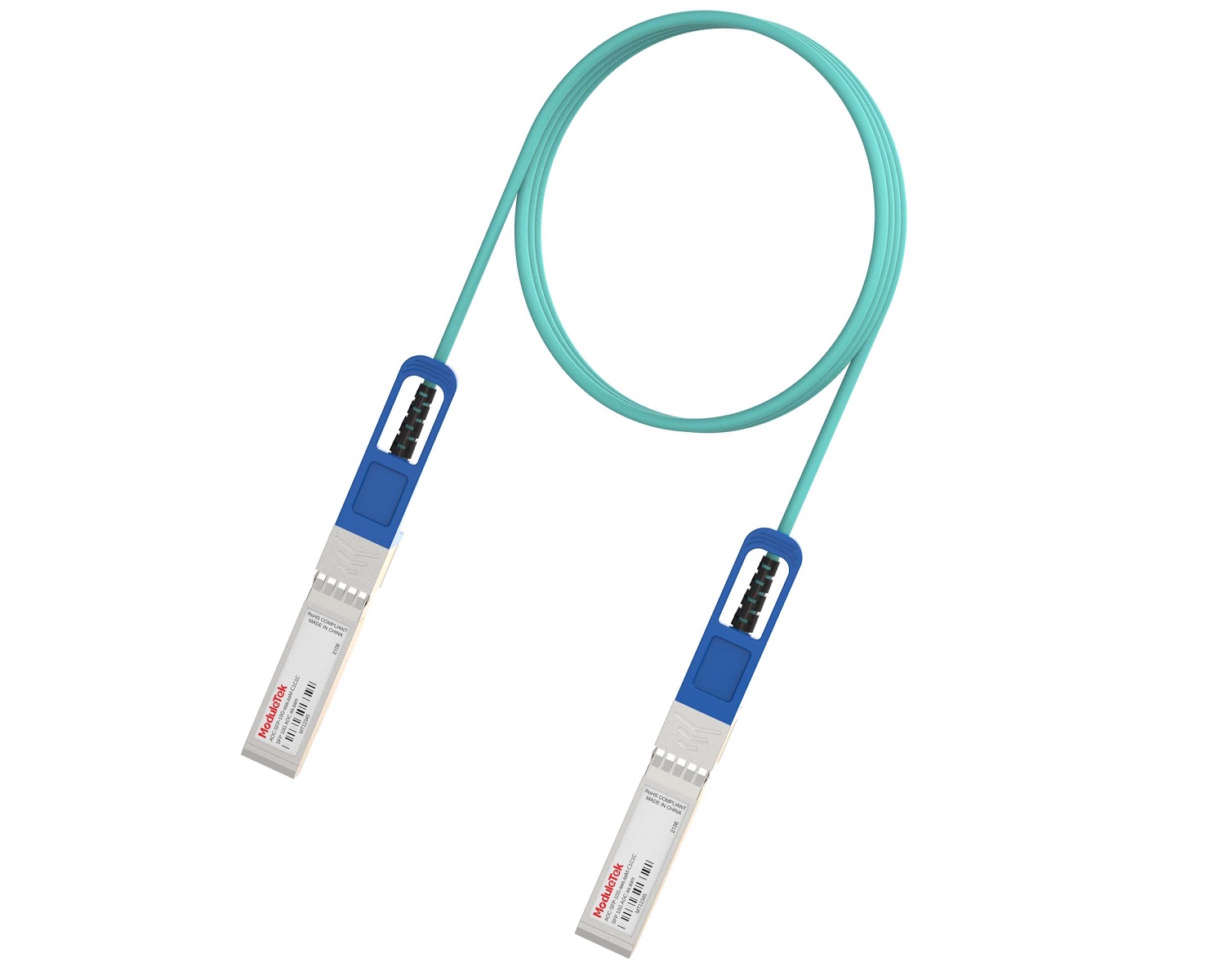 Full-Rate AOC & Breakout Series
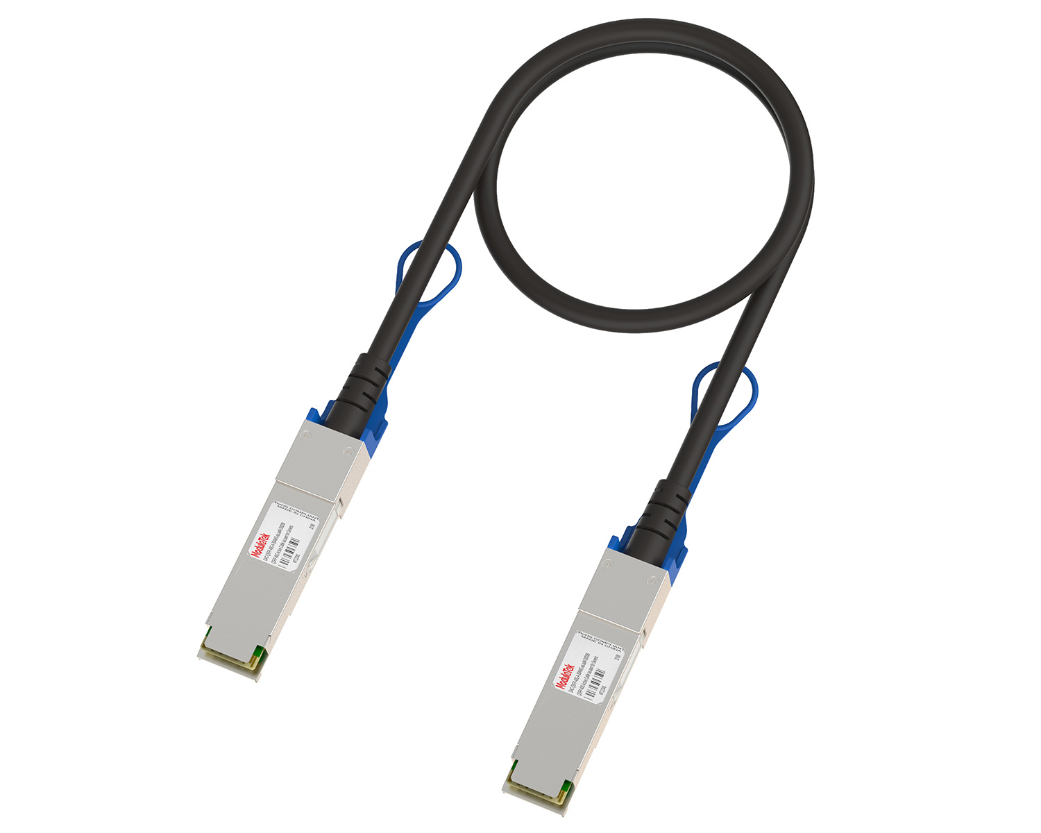 10G/40G Active DAC Series
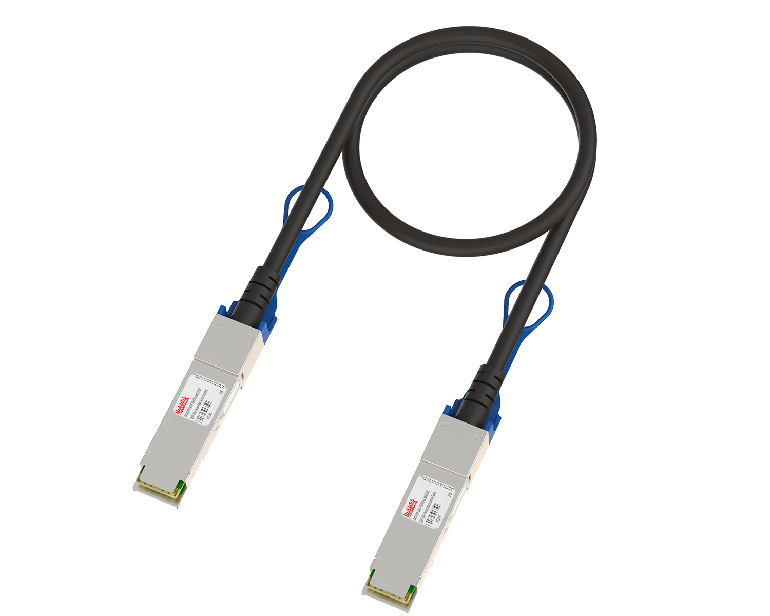 Full-Rate Passive DAC Series
 40G/100G Passive Breakout DAC Series
 Regular/MTP-MPO Fiber Patch Cords
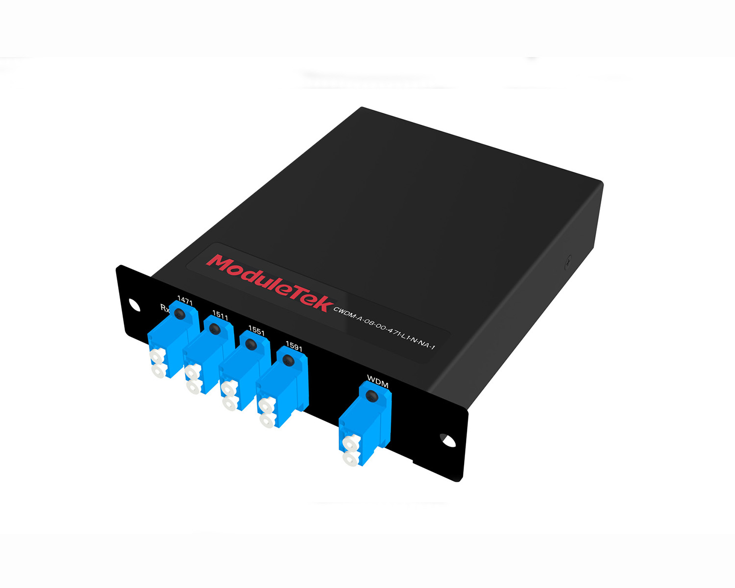 MT2011
 MT2010
 CodingBox
 QSFP to SFP Adapter
CWDM Long-Distance Transmission Solution
Time: 2021-11-09
I. Overview
In medium and long-distance fiber optic transmission applications (40km to 80km), CWDM transmission systems hold a significant market share. This paper briefly introduces the basics of CWDM and CWDM wavelength division multiplexers, focusing on two typical CWDM long-distance transmission solutions.
II. Introduction to CWDM Basics and WDM
1. Introduction to CWDM Basics
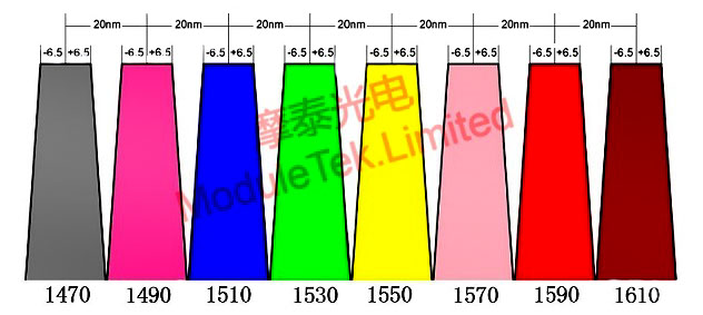
Figure 1 1470-1610nm 8-Channel CWDM Channel Wavelength Diagram
CWDM (Coarse Wavelength Division Multiplexing) is defined by ITU-T G.694.2 as having 18 wavelengths, ranging from 1270nm to 1610nm (e.g., 1270nm, 1290nm, ..., 1610nm) with a channel spacing of 20nm and a channel bandwidth of ±6.5nm. Generally, the last 8 channels (with center wavelengths of 1470nm, 1490nm, ..., 1610nm) are used for long-distance transmission (over 40km). CWDM optical modules require the emission wavelength to be controlled within ±6nm of the center wavelength to ensure the module's wavelength falls within the channel passband.
2. Introduction to Coarse Wavelength Division Multiplexers
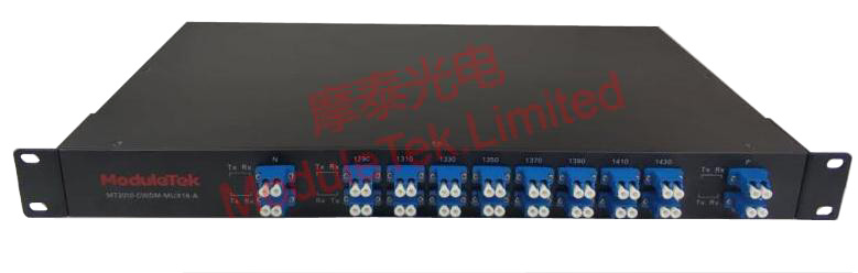
Figure 2 Product Photo of Moduletek 1U Chassis 8CH CWDM MUX&DEMUX
8CH CWDM MUX&DEMUX Technical Parameters:
• Model: MT2010-CWDM-MUX8-A
• Wavelength: 1470nm-1610nm
• Channel Spacing: 20nm
• Bandwidth: ±6.5nm
• Insertion Loss: ≤2.5dB (Note: Insertion loss unit is dB, not dBm)
• Adjacent Channel Isolation: ≥30dB
• Non-Adjacent Channel Isolation: ≥40dB
• Fiber Type: Dual Fiber
• Chassis: 19-Inch 1U Chassis
• Operating Temperature: -5°C ~ +75°C
III. CWDM Long-Distance Transmission Network Solutions
1. 2-Site Networking
Customer Requirements:
Two nodes with a link length of 60km, requiring 8×10Gbps bandwidth communication between the two sites.
Solution Design:
① After calculation, the total loss of the MUX (multiplexer) and fiber is ≤20dB. No optical amplifier is needed for the link, and the direct CWDM WDM transmission scheme provides a cost-optimal solution.
② Install an 8CH CWDM MUX&DEMUX (multiplexer & demultiplexer) at each of the two nodes to aggregate and transmit 8-channel signals.
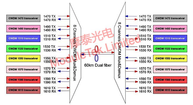
Figure 3 2-Node 60km CWDM WDM Transmission Solution Diagram
2. Multi-Site Networking
Customer Requirements:
A 55km-long link, with two intermediate nodes to be added at the 15km and 40km points, enabling mutual communication among four sites.
Solution Design:
① After calculation, the total loss of the MUX, OADM (Optical Add-Drop Multiplexer) and fiber is ≤20dB. No optical amplifier is needed for the link, and the CWDM WDM transmission scheme provides a cost-optimized solution.
② Install a 1CH OADM at each intermediate node to realize signal downloading and uploading respectively (OADM enables adding/removing specific wavelength channels without disrupting the main link).
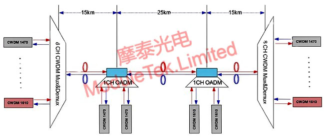
Figure 4 4-Node 55km CWDM WDM Transmission Solution Diagram
Moduletek provides the products mentioned in this application guide. Welcome to place your orders!
For further inquiries about the above content, please contact us at: sales@moduletek.com


