 40G/100G Optical Transceivers
 25G Optical Transceivers
 10G Optical Transceivers
 155M/2.5G Optical Transceivers
 1G Optical Transceivers
 1G BIDI Optical Transceivers
 Dual-Rate Optical Transceivers
 FC 16G/32G Optical Transceivers
 CWDM Optical Transceivers
 DWDM Optical Transceivers
 SGMII Port Optical Transceivers
 XFP Optical Transceivers
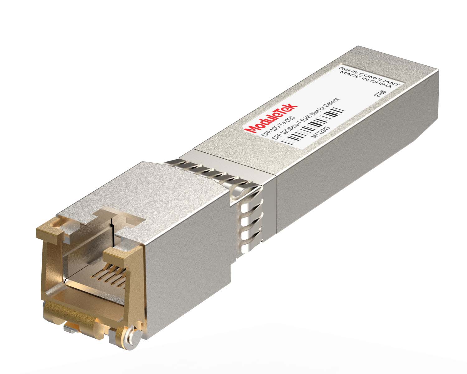 100M/1G/10G Coppers
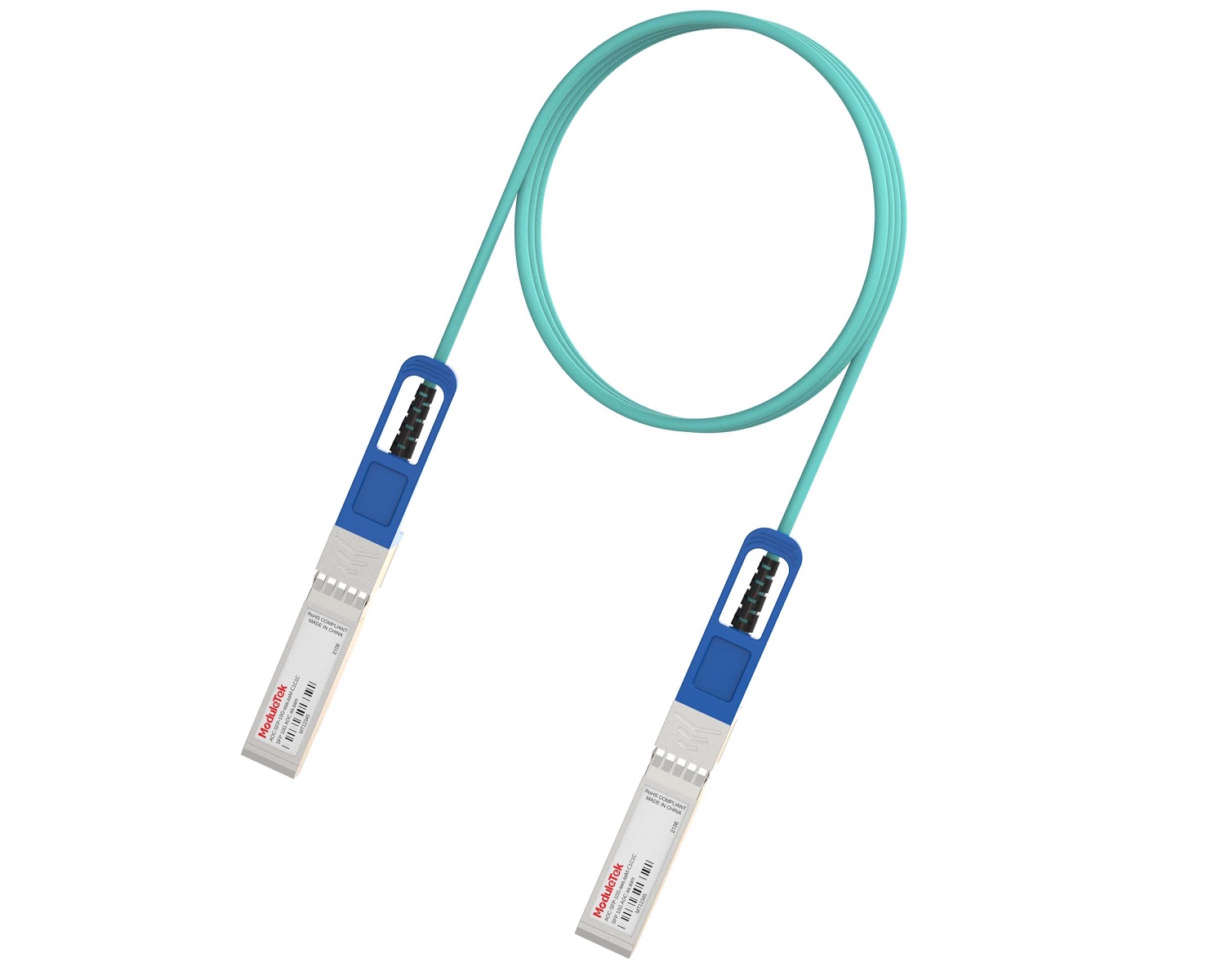 Full-Rate AOC & Breakout Series
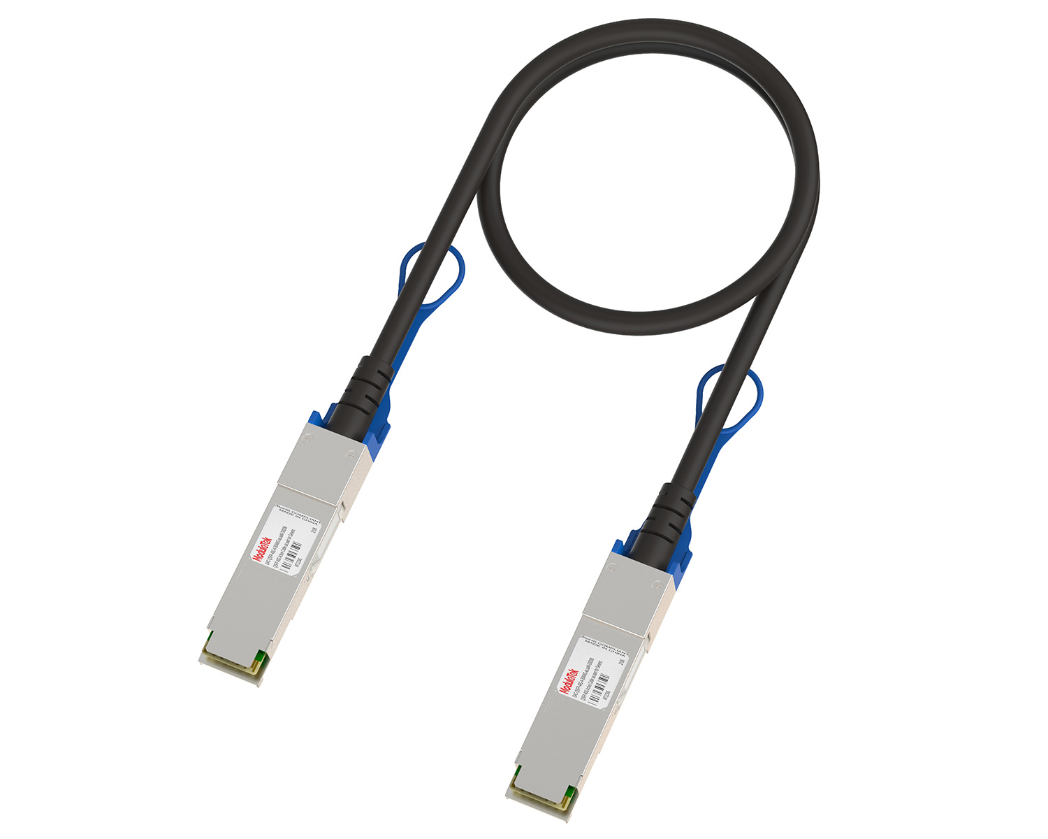 10G/40G Active DAC Series
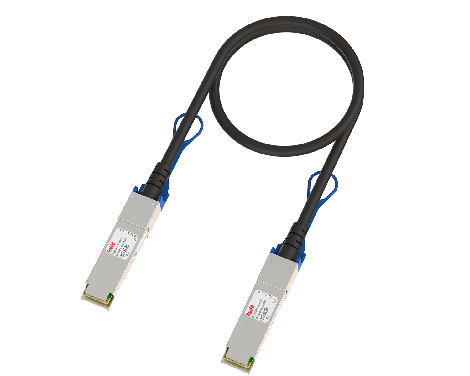 Full-Rate Passive DAC Series
 40G/100G Passive Breakout DAC Series
 Regular/MTP-MPO Fiber Patch Cords
 MT2011
 MT2010
 CodingBox
 QSFP to SFP Adapter
ADVA FSP150CC-825 Switch Showcase
Time: 2025-03-20
Moduletek Laboratory introduces the ADVA FSP150CC-825 switch in this document, covering three aspects: appearance, device management, and internal structure.
1. Product Introduction
The front panel of the ADVA FSP150CC-825 switch is equipped with 7×RJ45 ports, 3×SFP ports, 1×RJ45 serial port, 1×management port, and 2×power module slots. The rear panel features a DC power input port and cooling heat sinks, with air vents designed on both sides of the device. The official specifications and physical appearance of the switch are shown below.
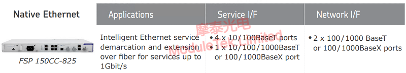
Figure 1 Official Description
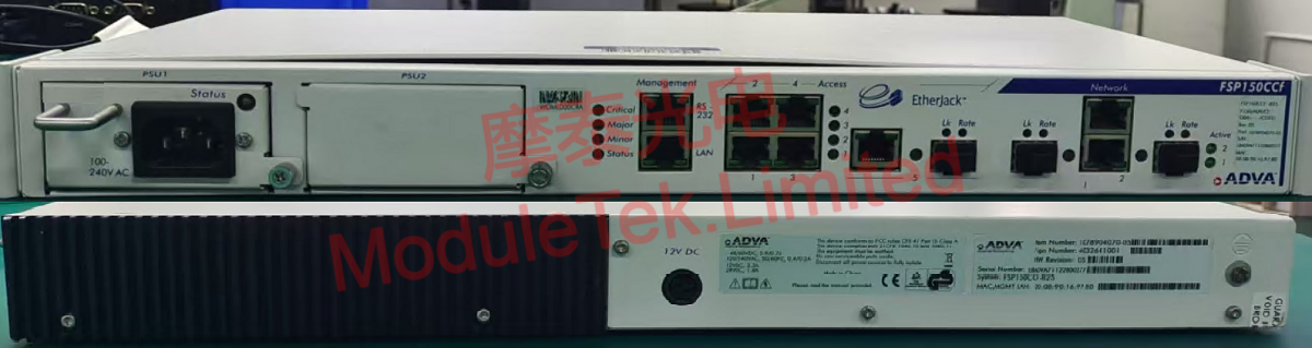
Figure 2 Front and Rear Panel Overview
2. Device Management
The ADVA FSP150CC-825 switch supports management via Command Line Interface (CLI) and Web Graphical User Interface (Web GUI). The CLI supports access through serial port, SSH, and Telnet.
Power-Up and Console Login
Connect the power cord to power on the device. Use an RJ45-to-DB9 serial cable to connect the PC to the switch’s serial port.
• Default baud rate: 9600
• Default login credentials: Username covaro1 / Password covaro#1
Log in with the above credentials to access the device console.
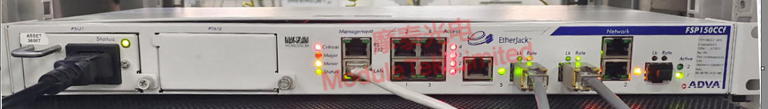
Figure 3 Device Power-Up
CLI Management
Connect a Moduletek SFP-GE-T module to the ADVA FSP150CC-825 switch using a patch cord. The module will establish a normal link, and the port indicator will light up. Execute the command below to view the interface status and module identification information:
show interface <port-number>
Web GUI Management
Connect your PC to the switch’s management port LAN with a network cable. The default management IP address is 192.168.0.2. Open a local browser, enter the IP address to access the Web management page, and the homepage will display device and system overview information.

Figure 4 Web GUI Homepage
Click the corresponding switch interface under the Configuration icon in the upper-left corner; the page will display the interface’s configuration, running status, and inserted module details.
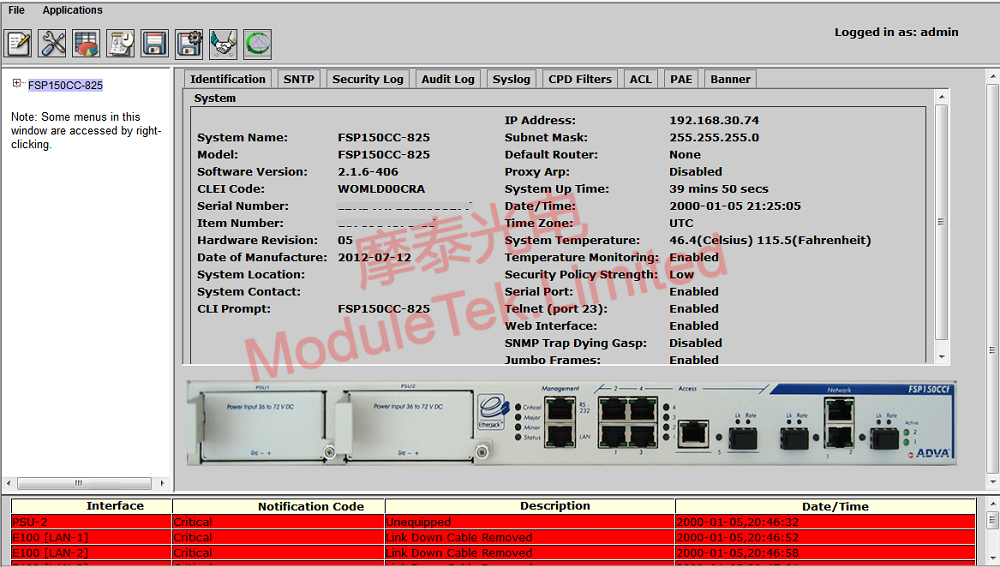
Figure 5 Interface Status Information Page
3. Disassembly & Internal Structure
Remove the top cover of the switch, and its internal structure is divided into two main parts:
1. Main PCB motherboard: Integrates various main chips, resistors, cooling components, and DC power supply circuits.
2. AC power supply board: Adopts a fanless design for stable operation.
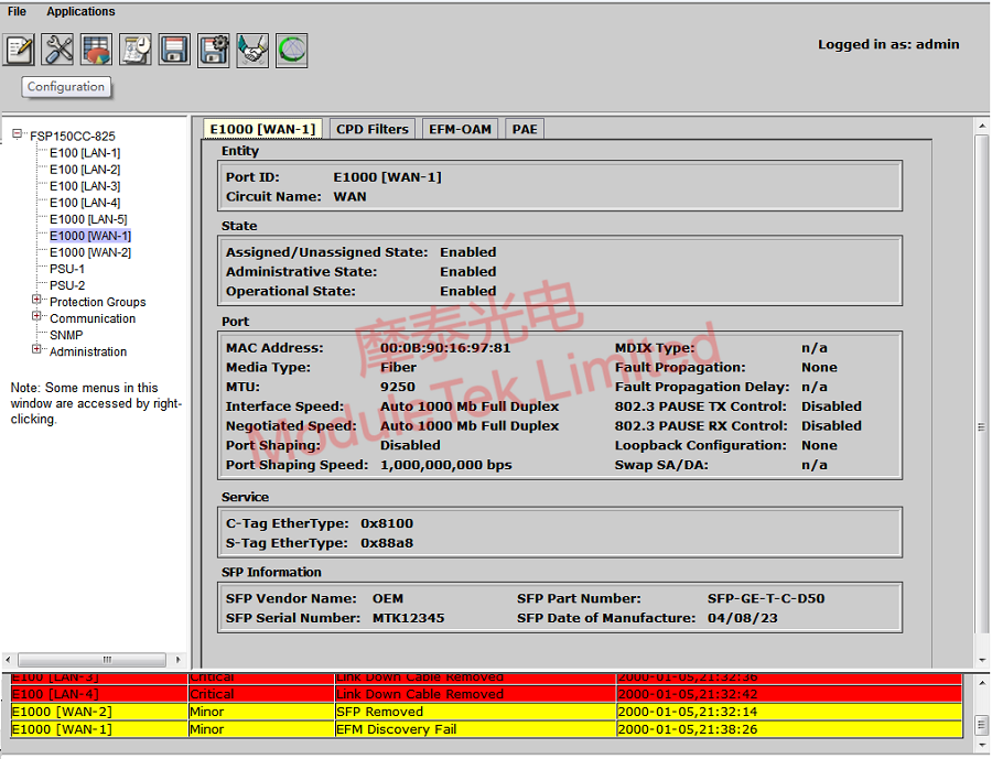
Figure 6 Internal Structure of FSP150CC-825
Two heat sinks are installed inside the device:
• One is a column-array heat sink, attached to the main chip and non-detachable.
• The other is a copper bar heat sink, under which is an XC4VLX80 chip — a Xilinx Virtex-4 series FPGA chip. This chip supports flexible logic configuration according to user needs, including digital signal processing, interface control, basic data forwarding, and simple VLAN partitioning.
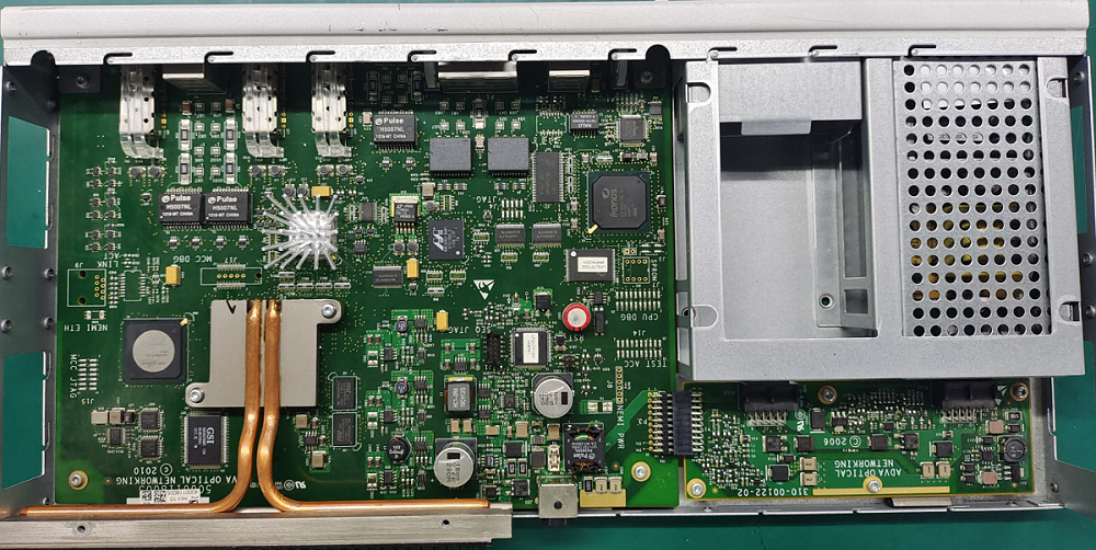
Figure 7 FSP150CC-825 Main Control Chip
A Marvell 88E3082-BAR1 PHY chip is located at the upper right of the main chip, supporting 8-port 10/100BASE-T Ethernet.
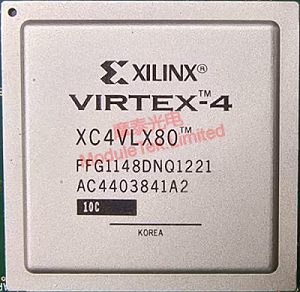
Figure 8 FSP150CC-825 PHY Chip
Moduletek optical modules are fully compatible with ADVA-related equipment. Welcome to inquire and purchase.
For further inquiries about the above content, please contact us at: sales@moduletek.com


