 40G/100G Optical Transceivers
 25G Optical Transceivers
 10G Optical Transceivers
 155M/2.5G Optical Transceivers
 1G Optical Transceivers
 1G BIDI Optical Transceivers
 Dual-Rate Optical Transceivers
 FC 16G/32G Optical Transceivers
 CWDM Optical Transceivers
 DWDM Optical Transceivers
 SGMII Port Optical Transceivers
 XFP Optical Transceivers
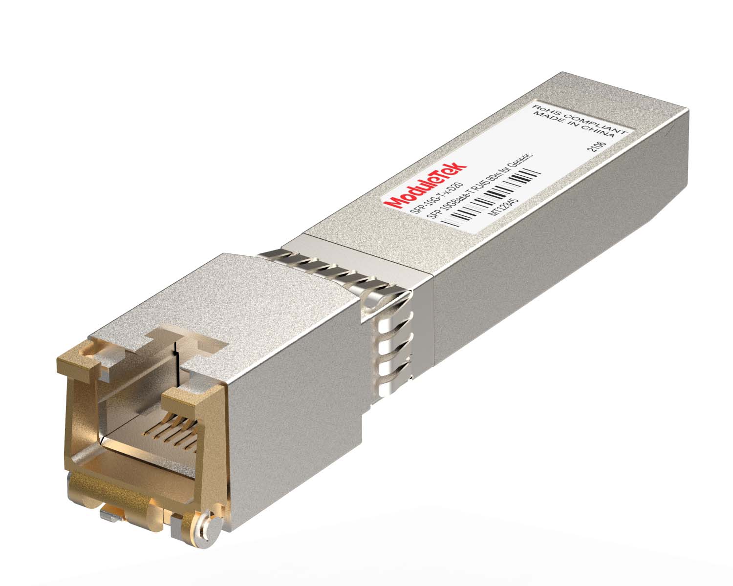 100M/1G/10G Coppers
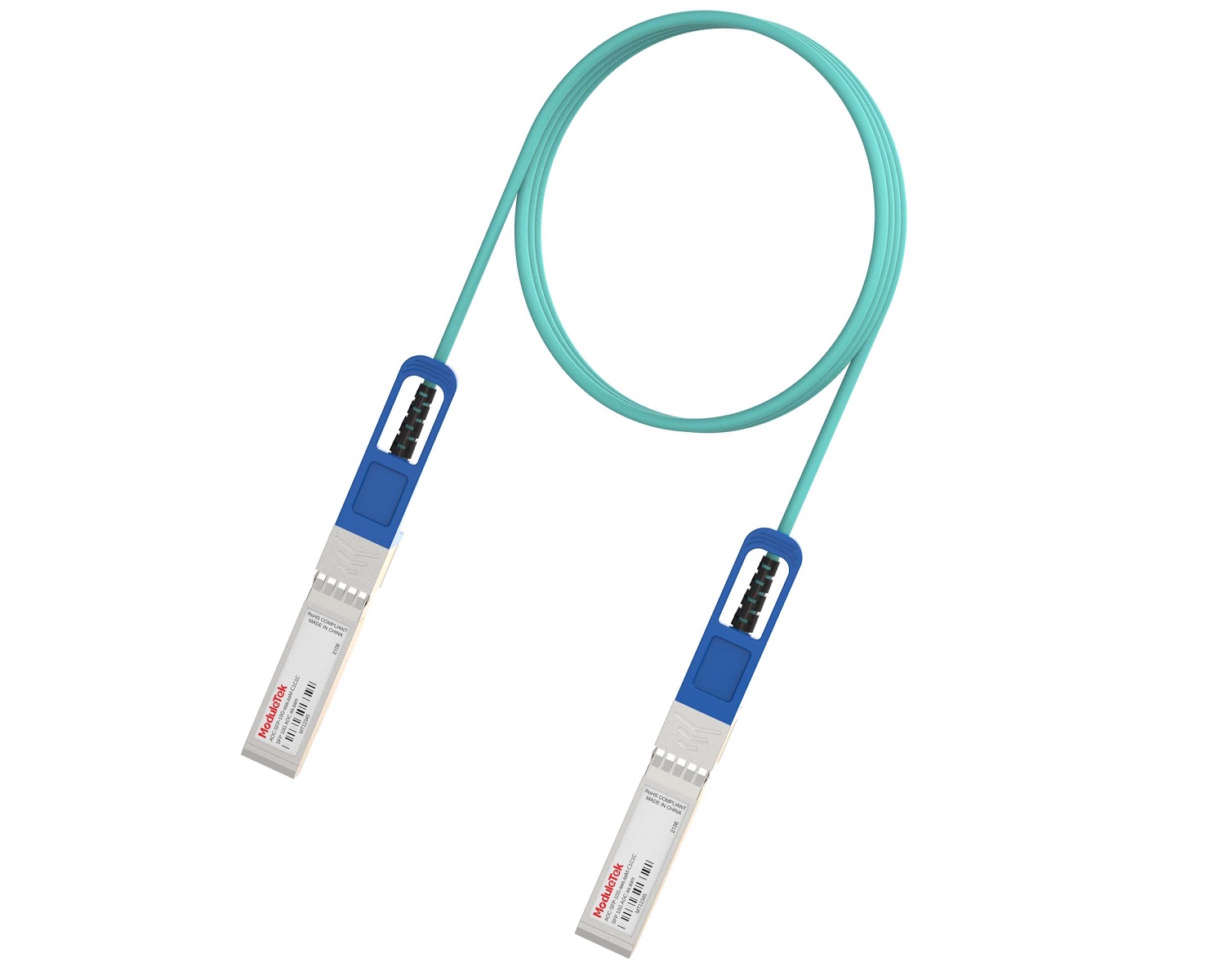 Full-Rate AOC & Breakout Series
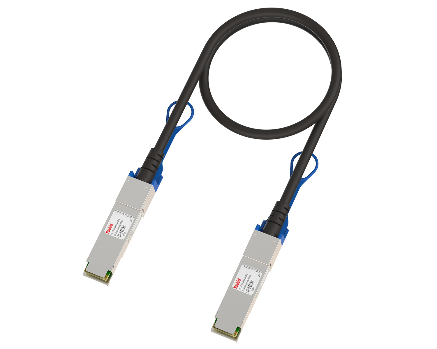 10G/40G Active DAC Series
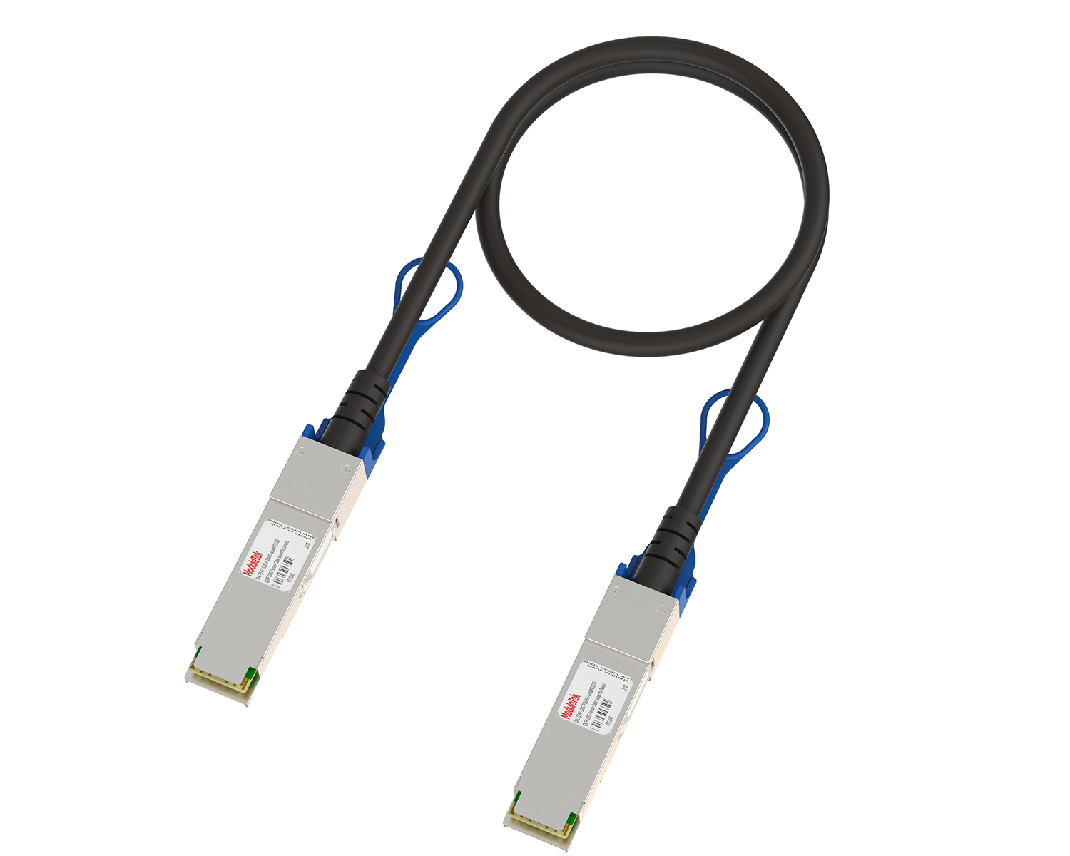 Full-Rate Passive DAC Series
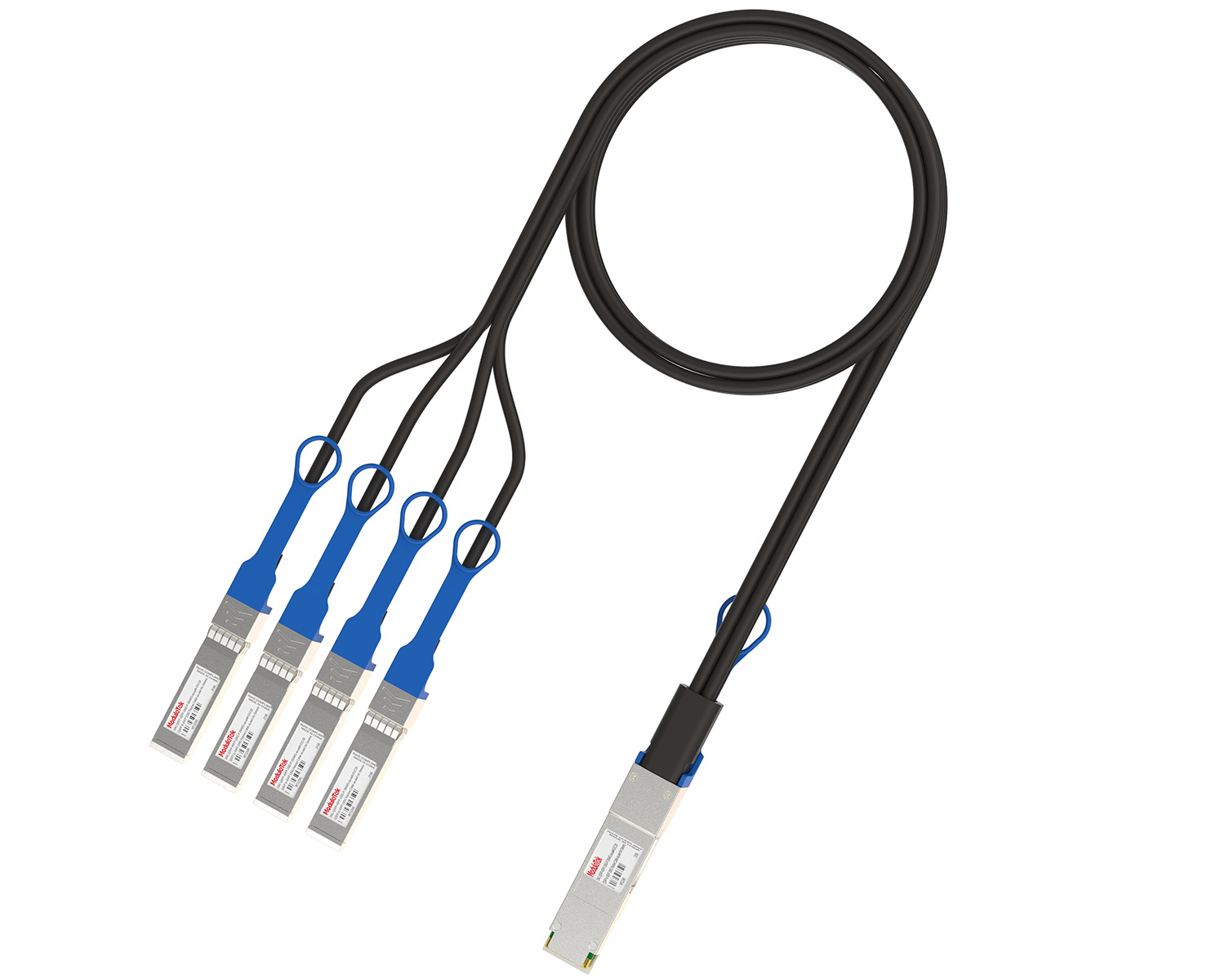 40G/100G Passive Breakout DAC Series
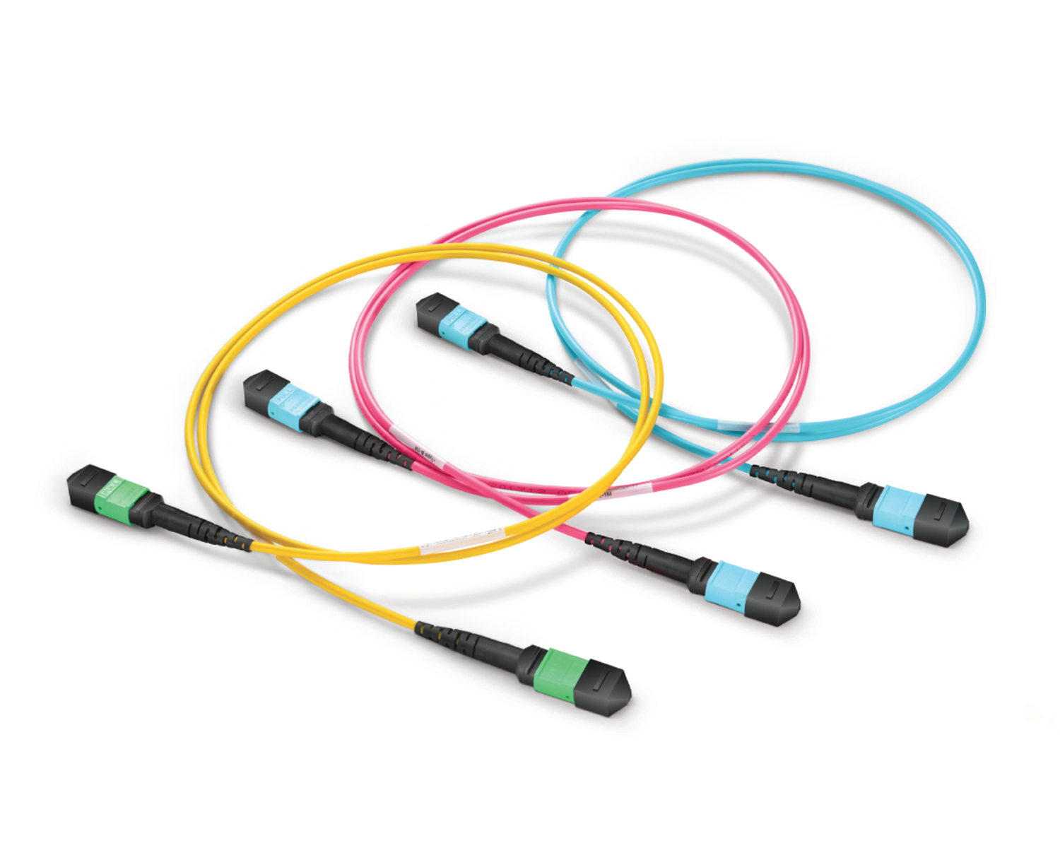 Regular/MTP-MPO Fiber Patch Cords
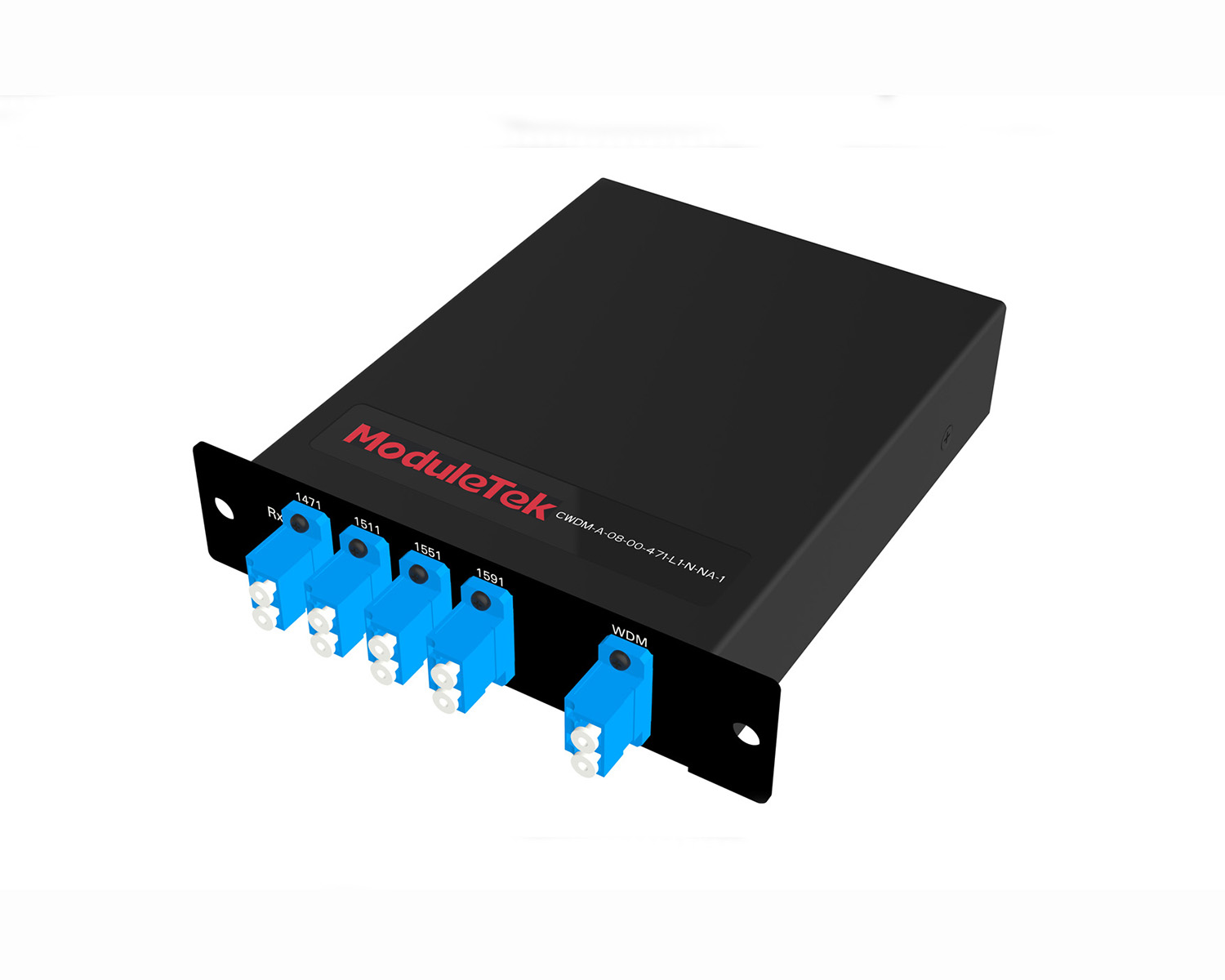 MT2011
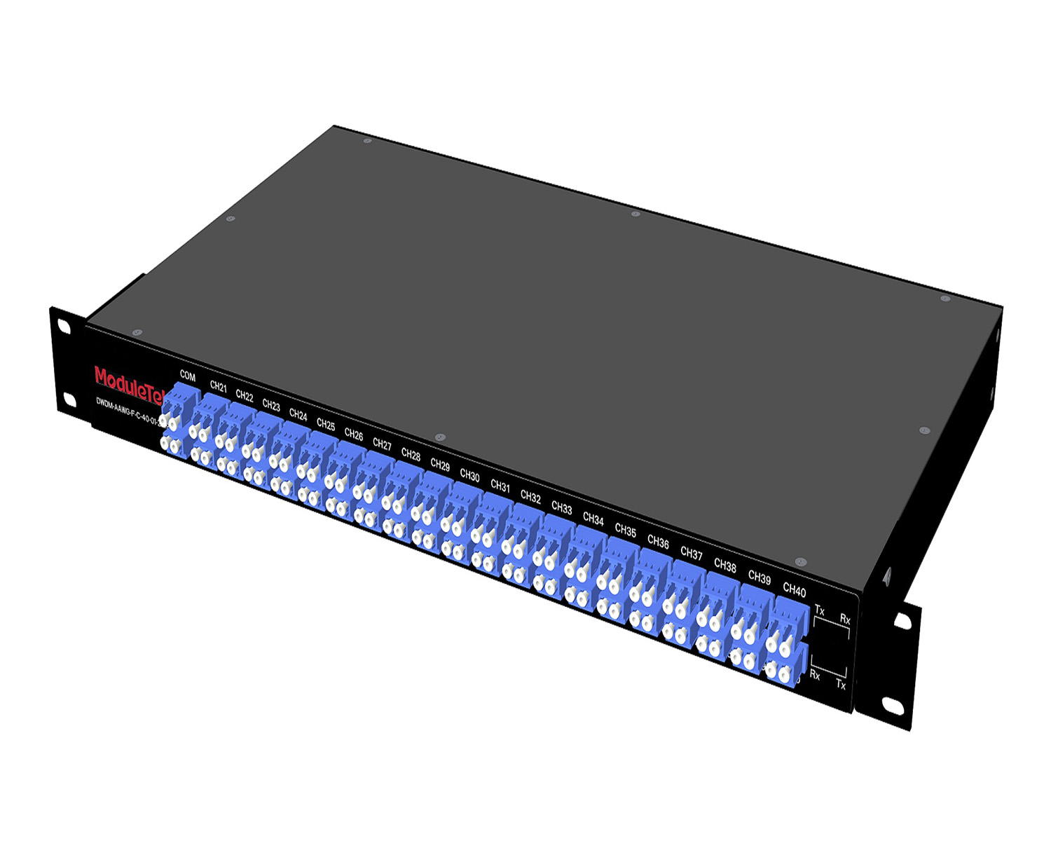 MT2010
 CodingBox
 QSFP to SFP Adapter
 首页 > Home > Application Notes > How To Configure Interface Breakout And Aggregation On Extreme X690 Series Switches
How To Configure Interface Breakout And Aggregation On Extreme X690 Series Switches
Time: 2025-09-12
This guide uses the Extreme X690 switch (Software Version: 22.4.1.4) as a test device to demonstrate how to configure QSFP interface breakout and aggregation on Extreme switches.
1. By default, QSFP interfaces work in aggregation mode. When checking interface information, one physical QSFP interface corresponds to four logical interfaces, which matches the port labeling on the device panel. Only the first logical interface is in Ready state at a default speed of 100G, while the other three are in Not Present state at a default speed of 25G.
2. Enter global configuration mode and run the following command to split aggregated QSFP interfaces:
configure ports <port_number> partition <split_mode>
Supported breakout modes include 2×50G, 4×10G, and 4×25G. After executing the command, save the configuration and reboot the device for the settings to take effect.
3. After completing the breakout configuration, check the interface status. All four logical interfaces will switch to Ready state, and each interface will run at the speed corresponding to the selected breakout mode (e.g., 10G).
4. To restore the interface to aggregation mode, enter global configuration mode and use the same command as Step 2. Set the partition mode to 1×40G or 1×100G. Save the configuration and reboot the device. The interface will revert to its default aggregated state.
Moduletek is at your service.
For further inquiries about the above content, please contact us at: sales@moduletek.com


